Asco Series 346 Vacuum Switch Bedienungsanleitung
- Typ
- Bedienungsanleitung

Mise en service - Installation - inbetriebnahme
VACUOSTAT REGLABLE G 1/4 ou à applique
ADJUSTABLE VACUUM SWITCH
with G 1/4 or bracket connections
EINSTELLBARER DRUCKSCHALTER, G 1/4 oder anreihbar
Series
Baureihe
346
1
32
V
(383 43 63)
MS-P800-15
1
32
V
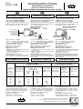
Vue de desssus du vacuostat (sans connecteur)
Vacuum Switch viewed from above (connector not fitted)
Druckschalter-Ansicht von oben (ohne Stecker)
RACCORDEMENT ELECTRIQUE
A standard 4 pin (3 + ground) disconnectable
connector is provided for connecting device to
the power supply. Cable outlet : CM10 (Pg11P)
The connector can be rotated by 90°.
ELECTRICAL DIAGRAM
• at rest : contact 1-2 made
• at work : contact 1-3 made
ELECTRICAL CONNECTION
Der elektrische Anschluβ erfolg über einen 4 -
poligen DIN-Stecker (3 + Masse). Kabel -
anschluβ CM10 (Pg11P). Stecker um jeweils
90° drehbar.
ELEKTRISCHE VERSCHALTUNG
• Ruhestellung : Kontakt 1 - 2 geschlossen
• Arbeitsstellung : Kontakt 1 - 3 geschlossen
ELEKTRISCHER ANSCHLUβ
Le raccordement électrique s'effectue par
connecteur débrochable normalisé 4 broches
(3+masse). Sortie de câble CM10 (Pg11P).
Connecteur orientable de 90° en 90°.
SCHEMA ELECTRIQUE
• Etat repos : contact 1-2 établi
• Etat actionné : contact 1-3 établi
POUVOIR DE COUPURE
RACCORDEMENT ELECTRIQUE
RACCORDEMENT PNEUMATIQUE
La construction du vacuostat offre deux possibi-
lités de raccordement pneumatique:
• Raccordement latéral taraudé G 1/4
• Raccordement inférieur à applique
L'appareil est fourni avec les bouchons et les
joints permettant le choix de l'un de ces modes
de raccordement en obturant l'autre orifice.
PNEUMATIC CONNECTION PNEUMATISCHER ANSCHLUSS
Die Konstruktion des Druckschalters bietet zwei
pneumatische Anschluβmöglichkeiten :
• Seitlicher Gewindeanschluβ G 1/4
• Aufflansch - Anschluβ von unten
Das Gerät wird mit Verschluβstopfen und
Dichtungen geliefert, wodurch der jeweils
gewünschte Anschluβ ermöglicht wird.
The vacuum switch is fitted with the two pneu-
matic connection systems described below :
• G 1/4 threaded system for lateral connection
• Bracket connection on base of unit
Supplied with the vacuum switch are plugs and
seals required for putting one of the systems into
service and blancking off the other.
CURRENT BREAKING CAPACITY
ELECTRICAL CONNECTION
MAX. SCHALTSTROM
ELEKTRISCHE DATEN
COURANT CONTINU
DIRECT CURRENT
GLEICHSTROMSCHALTLEISTUNG
COURANT ALTERNATIF
ALTERNATING CURRENT
WECHSELSTROMSCHALTLEISTUNG
Plage de réglage : -1 à 0 bar
Hystérésis : 0,1 bar en début de plage de réglage
0,2 bar en fin de plage de réglage
Contre-pression maxi : 16 bar
Position de montage : indifférente
Cadence maxi : 60 cycles/min
Température : -10°C, +85°C
Réglage du vacuostat
- Appliquer le niveau de vide désiré à l'orifice de
raccordement du vacuostat
- Tourner la vis de réglage jusqu'au changement d'état
- Serrer le contre-écrou
Vacuostat réglé (sur demande)
Aucune intervention n'est à faire, le vacuostat
est livré, réglé à un niveau de vide déterminé.
Pressure setting range : -1 to 0 bar
Hysteresis :
0,1 bar at start of pressure setting range
0,2 bar at the end of pressure setting range
Allowable back pressure : 16 bar
Mounting positions : all positions
Max. operating speed : 60 cycles per min.
Operating temperature : -10°C, +85°C
Setting the vacuum switch
- set desired vacuum level at vacuum switch
connection orifice
- turn pressure setting valve until energy level changes
- tighten locking-nut
Vacuum Switch is now Set (on request)
Once the vacuum switch has been set at the
determined vacuum level, no further operations
are necessary
Schaltdruckbereich : -1 bis 0 bar
Hysterese : 0,1 bar am Bereichsanfang
0,2 bar am Bereichsende
Max. Gegendruck : 16 bar
Einbaulage : beliebig
Max. Schaltzahl : 60, min.
-1
Temperaturbereich : -10°C, +85°C
Einstellen des Druckschalters
-
Den jeweiligen Anschluβ mit Vakuum beaufschlagen
- Verstellspindel bis zum Erreichen des
gewünschten Wertes drehen
- Kontermutter festziehen
Druckschalter fest eingestellt (auf Anfrage)
Keine weiteren Eingriffe sind mehr notwendig,
der Druckschalter ist auf den gewünschten
Druck eingestellt
Raccordement latéral
Lateral connection
Anschlu
ββ
ββ
β seitlich
Raccordement à applique
Bracket connection
Aufflansch - Anschlu
ββ
ββ
β
Vis de réglage du
point d'enclenchement
Engagement point
setting screw
Verstellspindel zur
Druckeinstellung
G1/4
Fermeture
Off
Öffner
(A)
Ouverture
On
Schlieβer
(A)
15 10 3 1,5 10 - - -
30 5 3 1,5 3 - - -
50 1 0,7 0,7 1 - - -
75 0,75 0,5 0,5 0,25 - - -
125 0,50 0,4 0,4 0,03 5 0,5 5
250 0,25 0,2 0,2 0,02 5 0,5 5
Charge résistive
Load resistance
Widerstandslast
(A)
Charge selfique
Inductance load
Induktive Last
(A)
Charge résistive
Load resistive
Widerstandslast
(A)
Charge selfique
Inductance load
Induktive Last
(A)
Lampe à
incandescence
Incandescent
lamp
Glühlampenlast
(A)
Lampe à incandescence
Incandescent lamp
Glühlampenlast
Tension
d'alimentation
Line
voltage
Versorgungs-
spannung
(V)
FR
GB
DE

Series
Baureihe
346
Mise en service - Installation - Inbetriebnahme
VACUOSTAT REGLABLE avec protection et visualisation
d'état G 1/4 ou à applique
ADJUSTABLE VACUUM SWITCH
with protection and status indicators G 1/4 or bracket connections
EINSTELLBARER DRUCKSCHALTER mit Schutz-und Leuchtdiode
G 1/4 oder anreihbar
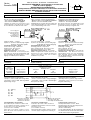
RACCORDEMENT PNEUMATIQUE
La construction du vacuostat offre deux possibi-
lités de raccordement pneumatique:
• Raccordement latéral taraudé G 1/4
• Raccordement inférieur à applique
L'appareil est fourni avec les bouchons et les
joints permettant le choix de l'un de ces modes
de raccordement en obturant l'autre orifice.
PNEUMATIC CONNECTION PNEUMATISCHER ANSCHLUSS
Die Konstruktion des Druckschalters bietet zwei
pneumatische Anschluβmöglichkeiten :
• Seitlicher Gewindeanschluβ G 1/4
• Aufflansch - Anschluβ von unten
Das Gerät wird mit Verschluβstopfen und
Dichtungen geliefert, wodurch der jeweils
gewünschte Anschluβ ermöglicht wird.
The vacuum switch is fitted with the two pneu-
matic connection systems described below :
• G 1/4 threaded system for lateral connection
• Bracket connection on base of unit
Supplied with the vacuum switch are plugs and
seals required for putting one of the systems into
service and blancking off the other.
ELECTRICAL CONNECTION
Connection by 1.5mm
2
cable. Connection
established using terminal connection under
transparent cover.
(non rotatable connector)
Check that product voltage complies with the
electrical supply voltage before switching on.
ELEKTRISCHER ANSCHLUSS
Anschluβ durch Kabel 1,5 mm
2
. Elektr.
Anschluβ mittels der unter der transparenten
Haube befindlichen Klemmen.
(Stecker nicht drehbar)
Vor der Inbetriebnahme die Übereinstimmung
der elektrischen Werte zwischen dem Druckschalter
und der Stromeinspeisung überprüfen.
Bornier du connecteur
Terminal connection
Klemmen im Stecker
Broches du Vacuostat
Vacuum switch pins
Anschluβ im Druckschalter
Connecteur - Connector - Stecker
Vacuostat - Vacuum switch - Druckschalter
Lampe à incandescence
Incandescence lamp
Glühlampenlast
Ouverture
On
Schlieβer
Fermeture
Off
Öffner
COURANT CONTINU
DIRECT CURRENT
GLEICHSTROMSCHALTLEISTUNG
Tension
d'alimentation
Line voltage
Versorguns-
spannung
Charge résistive
Load resistance
Widerstandslast
Charge selfique
Inductance load
Induktive Last
1,5 A
2 A
2 A2 A
24V (=)
SCHEMA ELECTRIQUE
Visualisation d'état par deux diodes
• Etat repos : contact 1-2 établi ; diode orange allumée
• Etat actionné : contact 1-3 établi ; diode rouge allumée
Déparasitage intégré
WIRING DIAGRAM
Status indicated by two diodes
• At rest : contact 1-2 made : orange diode lights
• At actuated : contact 1-3 made : red diode lights
Built parasit protection
ELEKTRISCHE VERSCHALTUNG
Sichtanzeige durch zwei Dioden
• Ruhestellung : Kontact 1-2 geschlossen, orange Leuchtdiode
• Arbeitsstellung : Kontact 1-3 geschlossen, rote Leuchtdiode
Integrierte Entstörung
1
32
V
(1) : 24V (=)
(2) : A2
(3) : A1
(4) : 0V
(5) : PE
RACCORDEMENT ELECTRIQUE
Raccordement par conducteur 1,5mm
2
maxi
Le raccordement électrique s'effectue par le
bornier situé sous le capot transparent.
(connecteur non orientable)
Avant mise sous tension, vérifier la concor-
dance de tension entre le produit et le réseau
d'alimentation.
Vis de réglage du
point d'enclenchement
Engagement point
setting screw
Verstellspindel zur
Druckeinstellung
Raccordement à applique
Bracket connection
Aufflansch - Anschlu
ββ
ββ
β
Raccordement latéral
Lateral connection
Anschlu
ββ
ββ
β seitlich
G 1/4
Pressure setting range : -1 to 0 bar
Hysteresis: 0,1 bar at start of pressure setting range
0,2 bar at the end of pressure setting range
Allowable back pressure : 16 bar
Mounting positions : all positions
Max. operating speed : 60 cycles per min.
Operating temperature : 0°C, +60°C
Setting the vacuum switch : see overleaf
NOTE : If required the vacuum switch can be
delivered set at the required vacuum-level
(given on the label). In this case no further
modification is possible
Schaltdruckbereich : -1 bis 0 bar
Hysterese : 0,2 bis 0,5 bar am Bereichsanfang
0,4 bis 1 bar am Bereichsende
Max. Gegendruck : 16 bar
Einbaulage : beliebig
Max. Schaltzahl : 60, min.
-1
Temperaturbereich : 0°C, +60°C
Einstellen des Druckschalters : seihe Rückseite
ANMERKUNG : Auf Wunsch kann der
Druckschalter bereits auf einen bestimmten
Wert eingestellt, geliefert werden (aufgeführt
auf der Geräteetikette). In diesem Fall ist die
Verstellspindel verriegelt.
Plage de réglage : -1 à 0 bar
Hystérésis : 0,1 bar en début de plage réglable
0,2 bar en fin de plage réglable
Contre-pression maxi : 16 bar
Position de montage : indifférente
Cadence maxi : 60 cycles/mn
Température : 0°C, +60°C
Réglage du vacuostat : voir au verso
NOTA : Sur demande, le vacuostat peut être
livré, réglé à un niveau de vide déterminé (indi-
qué sur l'étiquette de l'appareil). Dans ce cas le
réglage est condamné par un obturateur.
POUVOIR DE COUPURE (limité par le
connecteur)
RACCORDEMENT ELECTRIQUE ELECTRICAL CONNECTION ELEKTRISCHE DATEN
CURRENT BREAKING CAPACITY (limited
by the connector)
MAX. SCHALTSTROM (durch den stecker
begrenzt)
MS-P800-15
-
 1
1
-
 2
2


Asco Series 346 Vacuum Switch Bedienungsanleitung
- Typ
- Bedienungsanleitung
in anderen Sprachen
Verwandte Artikel
-
Asco Series 346 Pressure Switch Bedienungsanleitung
-
-
-
 joucomatic Series 349 Adjustable Vacuum Switch Bedienungsanleitung
-
-
 joucomatic Series 349 Adjustable Vacuum Switch Bedienungsanleitung
-
-

