
© 2017 STANLEY Black & Decker, Inc.
New Britain, CT 06053
U.S.A.
69924 8/2022 Ver. 19
USER MANUAL
Safety, Operation and Maintenance
EP30200
ELECTRONIC
PIN BRAZING UNIT

2 ► EP30200 User Manual
DECLARATION OF CONFORMITY
DECLARATION OF CONFORMITY
ÜBEREINSTIMMUNGS-ERKLARUNG
DECLARATION DE CONFORMITE CEE
DECLARACION DE CONFORMIDAD
DICHIARAZIONE DI CONFORMITA
Hydraulic Tools
______________________________________________________________________
I, the undersigned:
Ich, der Unterzeichnende:
Je soussigné:
El abajo firmante:
lo sottoscritto:
Weisbeck, Andy
Surname and First names/Familiennname und Vornamen/Nom et prénom/Nombre y apellido/Cognome e nome
hereby declare that the equipment specified hereunder:
bestätige hiermit, daß erklaren Produkt genannten Werk oder Gerät:
déclare que l’équipement visé ci-dessous:
Por la presente declaro que el equipo se especifica a continuación:
Dichiaro che le apparecchiature specificate di seguito:
1. Category: Pin Braze / Safebond Unit (Product Group-Railroad)
Kategorie:
Catégorie:
Categoria:
Categoria:
2. Make/Marke/Marque/Marca/Marca Stanley Hydraulic Tools
3. Type/Typ/Type/Tipo/Tipo: EP30 / EP60
4. Serial number of equipment:
Seriennummer des Geräts:
Numéro de série de l’équipement:
Numero de serie del equipo:
Matricola dell´attrezzatura:
All
Has been manufactured in conformity with
Wurde hergestellt in Übereinstimmung mit
Est fabriqué conformément
Ha sido fabricado de acuerdo con
E’ stata costruita in conformitá con
Directive/Standards
Richtlinie/Standards
Directives/Normes
Directriz/Los Normas
Direttiva/Norme
No.
Nr
Numéro
No
n.
Approved body
Prüfung durch
Organisme agréé
Aprobado
Collaudato
EMC Directive
SS-EN
2004/108/EC
60974-10
Self
Self
5. Special Provisions: None
Spezielle Bestimmungen:
Dispositions particulières:
Provisiones especiales:
Disposizioni speciali:
6. Representative in the Union: Patrick Vervier,Stanley Dubuis 17-19, rue Jules Berthonneau-BP 3406 41034 Blois Cedex, France.
Vertreter in der Union/Représentant dans l’union/Representante en la Union/Rappresentante presso l’Unione
Done at/Ort/Fait à/Dado en/Fatto a Stanley Hydraulic Tools, Milwaukie, Oregon USA Date/Datum/le/Fecha/Data 1-10-11
Signature/Unterschrift/Signature/Firma/Firma
Position/Position/Fonction/Cargo/Posizione Director of Product Development

EP30200 User Manual ◄ 3
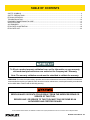
TABLE OF CONTENTS
SERVICING: This manual contains safety, operation and routine maintenance instructions. STANLEY Infrastructure
recommends that servicing of hydraulic tools, other than routine maintenance, must be performed by an authorized
and certied dealer. Please read the following warning.
To ll out a product warranty validation form, and for information on your warranty,
visit www.stanleyinfrastructure.com and select the Company tab > Warranty.
Note: The warranty validation record must be submitted to validate the warranty.
SERIOUS INJURY OR DEATH COULD RESULT FROM THE IMPROPER REPAIR OR
SERVICE OF THIS TOOL.
REPAIRS AND / OR SERVICE TO THIS TOOL MUST ONLY BE DONE BY AN
AUTHORIZED AND CERTIFIED DEALER.
For the nearest certied dealer, call STANLEY Infrastructure at (503) 659-5660 and ask for a Customer Service Representative.
SAFETY SYMBOLS ..................................................................................................................................................4
SAFETY PRECAUTIONS ..........................................................................................................................................5
EP30200 OPERATION .............................................................................................................................................. 6
TROUBLESHOOTING ............................................................................................................................................10
EQUIPMENT MAINTENANCE & CARE .................................................................................................................. 11
SPECIFICATIONS ................................................................................................................................................... 12
ACCESSORIES.......................................................................................................................................................13
EP30 PARTS ILLUSTRATION.................................................................................................................................19
EP30 PARTS LIST...................................................................................................................................................20

4 ► EP30200 User Manual
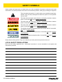
Always observe safety symbols. They are included for your safety and for the protection of the tool.
LOCAL SAFETY REGULATIONS
Enter any local safety regulations here. Keep these instructions in an area accessible to the operator and
maintenance personnel.
Safety symbols and signal words, as shown below, are used to emphasize all operator, maintenance and repair
actions which, if not strictly followed, could result in a life-threatening situation, bodily injury or damage to equipment.
This is the safety alert symbol. It is used to alert you to potential personal injury
hazards. Obey all safety messages that follow this symbol to avoid possible
injury or death.
This safety alert and signal word indicates an imminently hazardous situation
which, if not avoided, will result in death or serious injury.
This safety alert and signal word indicates a potentially hazardous situation
which, if not avoided, could result in death or serious injury.
This safety alert and signal word indicates a potentially hazardous situation
which, if not avoided, could result in death or serious injury.
This signal word indicates a potentially hazardous situation which, if not avoided,
may result in property damage.
This signal word indicates a situation which, if not avoided, will result in damage
to the equipment.
This signal word indicates a situation which, if not avoided, may result in damage
to the equipment.
SAFETY SYMBOLS

EP30200 User Manual ◄ 5
Always observe safety symbols. They are included for your safety and for the protection of the tool.
LOCAL SAFETY REGULATIONS
Enter any local safety regulations here. Keep these instructions in an area accessible to the operator and
maintenance personnel.
Safety symbols and signal words, as shown below, are used to emphasize all operator, maintenance and repair
actions which, if not strictly followed, could result in a life-threatening situation, bodily injury or damage to equipment.
This is the safety alert symbol. It is used to alert you to potential personal injury
hazards. Obey all safety messages that follow this symbol to avoid possible
injury or death.
This safety alert and signal word indicates an imminently hazardous situation
which, if not avoided, will result in death or serious injury.
This safety alert and signal word indicates a potentially hazardous situation
which, if not avoided, could result in death or serious injury.
This safety alert and signal word indicates a potentially hazardous situation
which, if not avoided, could result in death or serious injury.
This signal word indicates a potentially hazardous situation which, if not avoided,
may result in property damage.
This signal word indicates a situation which, if not avoided, will result in damage
to the equipment.
This signal word indicates a situation which, if not avoided, may result in damage
to the equipment.
• Tool operators and maintenance personnel must
always comply with the safety precautions given in
this manual and on the stickers and tags attached to
the tool and hose.
• These safety precautions are given for your safety.
Review them carefully before operating the tool and
before performing general maintenance or repairs.
• Supervising personnel should develop additional
precautions relating to the specic work area and
local safety regulations. If so, place the added
precautions in the space provided in this manual.
• This tool will provide safe and dependable service if
operated in accordance with the instructions given
in this manual. Read and understand this manual
and any stickers and tags attached to the tool before
operation. Failure to do so could result in personal
injury or equipment damage.
• Operator must start in a work area without
bystanders. The operator must be familiar with all
prohibited work areas such as excessive slopes,
dangerous terrain conditions and rail trafc.
• Establish a training program for all operators to
ensure safe operation.
• Do not operate the tool unless thoroughly trained or
under the supervision of an instructor.
• Always wear safety equipment such as goggles,
ear, head protection and respiratory protection at all
times when operating the tool.
• Do not inspect or clean the tool while the battery
power source is connected. Accidental arcing can
cause serious injury.
• Do not load brazing pins or ceramic rings while
the battery power source is connected. Accidental
arcing can cause serious injury.
• Do not use the tool while it is connected to a battery
charger.
• Ensure battery charging is only done in a dry
environment. Charging batteries in the rain or near
standing water presents an electrocution hazard.
Read the safety and operation instructions provided
with the battery charger before using the battery
charger.
• Do not operate a damaged, improperly adjusted or
incompletely assembled tools.
• To avoid personal injury or equipment damage,
all tool repair, maintenance and service must only
be performed by authorized and properly trained
personnel.
• Do not exceed the rated limits of the tool or use the
tool for applications beyond its design capacity.
• Always keep critical tool markings, such as labels
and warning stickers, legible.
• Always replace parts with replacement parts
recommended by STANLEY.
SAFETY PRECAUTIONS

6 ► EP30200 User Manual
GENERAL PROTECTION
Store the Electronic Pin Brazing Unit in a place where it is
protected from the elements, abrasive dust and damage.
Use only recommended replacement parts and materials
specied in the Parts List section of this manual.
Use only recommended accessories specied in the Parts
List section of this manual.
Do not use the Electronic Pin Brazers for applications it was
not designed for.
Use the carrying handle to transport the unit.
CLEANING
Establish a routine to keep the unit as free from dirt as pos-
sible – daily, or at each shift change.
Pin Brazers exposed to rain, sand or grit-laden air should be
cleaned prior to each use.
Keep tool labels and stickers legible.
PREPARATION PROCEDURES
Before putting a new Pin Brazer into initial service, or after an
extended period of being unused, perform a visual inspection
for bent, broken, cracked, missing or worn components.
INITIAL SETUP AND BATTERY CHARGING
Failure to follow the instructions in the battery
charger operation manual can result in battery
explosion and serious bodily injury. To reduce the
risk of battery explosion, read and understand the
safety and operation instructions in the battery
charger operation manual, the instructions
published by the battery manufacturer and the
instructions in this manual before attempting to
charge the batteries.
Make sure battery charging is only accomplished in a
well ventilated room. DO NOT PLACE THE CONTROL
BOX ON TOP OF THE BATTERIES. REMOVE THE
BATTERY BOX COVER. Battery charging
produces explosive gases. A battery explosion
can cause serious injuries. Avoid battery
explosions by keeping cigarettes, sparks and
flames away from batteries during charging.
Always wear safety glasses when working with
batteries.
1. The three batteries furnished are sealed, maintenance
free batteries.
Sealed, maintenance free batteries do not contain cell caps
and are already lled with battery acid. They will require
charging before use.
Use only battery charger specially made for pin
brazing units (36V DC) approved by STANLEY.
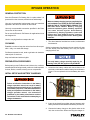
2. Locate the four battery cables and connect them to the
terminals on the batteries and the battery box as shown in
Figure 1. Do not replace the lid on the battery box at this
time.
+Pos.
-Neg.
Figure 1: Battery cable and terminals
3. Insert the enclosed foam-rubber spacers between each
battery and at both ends between the battery and the unit.
4. Connect the battery charger to the grinder outlet on the
unit, then to the mains. When removing the charger re-
EP30200 OPERATION

EP30200 User Manual ◄ 7
move the main rst, then remove the plug from the unit.
5. Batteries will fully charge in approximately 3-5 hours.
Follow the instructions in the battery charger manual to
complete the charging process.
6. Plug the two cable leads from the adapter box into the
battery box.
7. Insert the plug from the battery charger into the grinder
outlet on the adapter box.
8. Plug the battery charger into a standard 110 Volt AC
outlet.
9. Follow the instructions in the battery charger manual to
complete the charging process.
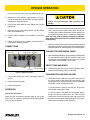
CONNECTIONS
Grinder Receptacle Control Cable
Female Socket
Gun Power Supply
Receptacle
Ground Receptacle
1 A Fuse
15 A Fuse
Pin Size Switch
Figure 2: EP30 Connections
1. Connect the brazing gun, power and trigger cables to
the unit.
2. Connect the ground cable.
3. Connect the grinder.
OPERATION
Prepare the rail surface
Select the type and length of bonding cable to use for the
bond. Use it as a guide to determine where brazing points
on the rail will be required.
Always use eye protection when grinding and
brazing.
1. Grind the surface of the rail where brazing is going to be
done, until the surface shows shiny metal, free of rust,
corrosion, pits or other contamination. When grinding, use
the edge of the grinding wheel - not the face of the wheel.
Note: Use only grinding wheels furnished by STANLEY.
Other wheels have shown to leave residues which cause
faulty brazing.
2. Grind the surface of the rail where the grounding cable will
be placed to ensure a good ground. The grounding cable
should be placed in close proximity to the brazing area.
PLACING THE GROUNDING CABLE
3. When nished grinding the rail, place the grounding cable
on the cleaned surface and then insert the other end
into the twist lock receptacle, in the control box marked
"GROUND" or "EARTHING". Twist to lock.
SELECT PINS AND RINGS
4. Select brazing pins and ceramic rings to match the speci-
cations of the bonding cable you selected.
CHANGING PIN AND RING HOLDER
5. Check that the pin holder and ring holder on the gun are
the correct sizes for the brazing pins and ceramic rings
you selected. If the sizes are incorrect, the pin holder and
ring holder can be changed as follows:
a. The ring holder is "push t" onto the gun. To remove it
from the gun, simply pull it away.
b. The pin holder is threaded onto a threaded shaft in
the gun and locked in place with a nut. Place an open
end wrench over the nut and an open end wrench over
the ats on the pin holder. While holding the nut in place,
unscrew the pin holder counter clockwise.
EP30200 OPERATION

8 ► EP30200 User Manual
Pin Holder Ring Holder
Figure 3. Pin and Ring Holder
c. Install the correct pin holder and tighten it securely
against the nut.
Never twist the axle when mounting the
pin holder.
d. Install the correct ring holder by placing it over the pin
holder and into the circular groove in the gun. Push it to
seat it in place.
LOADING PIN AND RING
6. Insert the brazing pin into the pin holder. The rounded tip
should be facing away from the gun.
7. Insert the ceramic ring into the ring holder. The serrated
edge should be facing away from the gun. See Figure 4.
Figure 4: Loading pin and ring
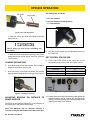
ADJUSTING BRAZING PIN DISTANCE TO
BRAZE SURFACE
The BG10100 automatically adjusts the correct distance of
the brazing pin to the surface to be brazed.
Note: The BG10100 may be adjusted manually if
necessary using the dial located on the back of the gun.
The settings are as follows:
+ = 2.5 mm distance
0 = 2.0 mm distance (normal position)
- = 1.5 mm distance
Dial
Figure 2: Gun Adjustment Dial
8. Plug the two gun cables into the appropriate outlets on
the control box.
SET CONTROL FOR PIN SIZE
9. Set the PIN TYPE switch on the control box for the
appropriate pin type being used. See Figure 3 below.
Brazing Pin Setting
8 mm Std P1
8 mm Extra P2
9.5 mm P3
Switch
Figure 3: Pin Type Control Switch
10. Position the terminal lug of the bonding cable against the
cleaned surface of the rail. Position the gun against the
cable lug so that the brazing pin is at the top edge of the
cable lug hole. See Figure 4 below.
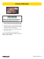
EP30200 OPERATION

EP30200 User Manual ◄ 9
Figure 4: Gun position
Make sure the correct ferrule and brazing pin are
used. The pin braze must be made in the top of
the hole when brazing to a vertical surface.
1. Hold the gun rmly with both hands and pull the trigger
once. The electronics will nish the braze automatically.
2. Hold the gun in place for 3-4 seconds after the brazing
is complete to allow for cooling. Then remove the gun
straight backwards, without pulling trigger.
3. After the braze has cooled, knock the shank off the braz-
ing pin using a hammer.
4. Use a new ceramic ring for each new pin braze.
Note: A red light indicates low batteries on the unit.
Charge as soon as possible.
EP30200 OPERATION

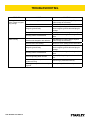
10 ► EP30200 User Manual
PROBLEM CAUSE SOLUTION
Brazing pin does not
ignite or does not ignite
long enough.
Batteries not charged or are defective. Test batteries for proper charge. Replace
and/or charge as necessary.
Blown fuse. Check fuses.
Magnetic ground faulty.
Ensure the grounding surface is clean.
Check magnetic ground cable and plug for
damage.
Faulty cables. Check gun cables and plugs for damage.
Bonding surface contaminated. Check that the brazing surface is ground
clean.
Braze is faulty. Batteries not charged or are defective. Test batteries for proper charge. Replace
and/or charge as necessary.
Incorrect PIN TYPE setting. Check PIN TYPE setting on the control box.
Magnetic ground faulty.
Ensure the grounding surface is clean.
Check magnetic ground cable and plug for
damage.
Bonding surface contaminated. Check that the brazing surface is ground
clean.
Incorrect grinding wheel is used. Use only Tyrolit grinding wheels or carbide
burr.
Ceramic ring was not positioned
square to the lug. Ensure ring is positioned correctly.
Brazing pin not positioned correctly in
lug hole.
Ensure pin is positioned correctly.
TROUBLESHOOTING

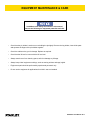
EP30200 User Manual ◄ 11
• Check that the pin holder is not burnt or not holding the pin tightly. Remove the ring holder, clean all the parts
and squeeze the ngers of the pin holder together.
• Check the cables on the gun for damage. Replace as required.
• Check that the lift level is correct with the lift level tool.
• Always store the tool in a clean dry space, safe from damage or pilferage.
• Always keep critical equipment markings, such as warning stickers and tags, legible.
• Equipment repair should be performed by experienced personnel only.
• Do not use the equipment for applications for which it was not intended.
In addition to the Safety Precautions in this manual,
observe the following for equipment protection and care.
EQUIPMENT MAINTENANCE & CARE

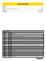
12 ► EP30200 User Manual
EP30200
Voltage..............................................................................................................................................................................................36V DC
Approximate Number of Brazings per Battery Charge ........................................................................................................................ 40-60
Weight .....................................................................................................................................................................................44 lbs / 20 kg
Overall Length .................................................................................................................................................................. 12.5 in. / 315 mm
Overall Width .................................................................................................................................................................... 8.75 in. / 220 mm
Overall Height ...................................................................................................................................................................... 16 in. / 400 mm
SPECIFICATIONS
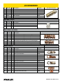
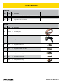
ACCESSORIES
Item
No. Part No. Qty Description
1 72974 1 Carrying Case
2 EP30K110 1 Pin Brazing Kit, 110vac. Kit Includes: BG10100 pin brazing gun, EP30200 pin brazing unit, DCG426M2 DeWalt grinder
kit, battery charger, 3 batteries, 73358 carbide burr.
3 35866 1 Battery Charger
4 40409 3 Battery, Genesis 16 amp, 12v
5 72776 4 Non-spillable Battery Label
6 73358 1 Carbide Burr SF-5
7 EP30200 1 Medium Duty Elec. Pin Brazing Unit (No Gun)
8 BG10100 1 Pin Brazing Gun
10 EP30K12110 1 Pin Brazing Kit 110V/12VDC. Kit Includes: BG10100 Pin brazing gun, EP30200 pin brazing unit, DCG426M2 DeWalt
grinder kit, extension cables, battery charger, 3 batteries, 800 Watt inverter, carrying case, 73358 carbide burr.
11 73358 1 Carbide Burr (1/4 in. Shank)
12 72974 1 Carrying Case
13 35818 1 Extension Cable for S4 Pistol
14 35819 1 Extension Cable for Earth 5m
15 35866 1 Battery Charger
16 40409 3 Battery, Genesis 16A 12V (3)
17 84936 1 Inverter 1000 Watt
18 72776 1 Non-spillable Battery Label
19 EP30200 1 Medium Duty Elec. Pin Brazing Unit
20 BG10100 1 Pin Brazing Gun

EP30200 User Manual ◄ 13
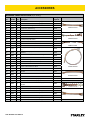
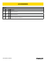
ACCESSORIES
STANDARD BRAZING PINS
Item
No. Part No. Qty Description
Ceramic Ring
Required
1 35835 1 8mm 35832
2 35836 1 8mm with extra silver 35832
3 35837 1 9.5mm 35833
4 35840 1 M8/12 threaded 35834
5 35841 1 M10 threaded 35834
6 35839 1 M12 threaded 35834
For use on rail only!
CERAMIC RINGS
Item
No. Part No. Qty Description
7 35832 1 8mm
8 35833 1 9.5mm
9 35834 1 12mm
PIN & RING HOLDERS
Item
No. Part No. Qty Description
10 35826 1 Pin Holder for Pin brazing, 8-9,5 mm brazing pins.
11 35827 1 Pin Holder for Pin brazing, M8 Threaded pins.
12 35828 1 Pin Holder for Pin brazing, M10 Threaded pins.
13 35829 1 Pin Holder for Pin brazing, M12 Threaded pins.
14 35825 1 Extended pin and ring holder set for 8-9,5 mm brazing pins.
15 35830 1 Ring Holder, 8-9,5 mm ceramic rings.
16 35831 1 Ring Holder, M8/M10/M12 mm ceramic rings.
CABLE LUGS
Item
No Part No. Qty Description
Brazing Pin
Required
17 47523 1 Braze Lug for 25 mm Cable 35836
18 47524 1 Braze Lug for 35 mm Cable 35836
19 47525 1 Braze Lug for 50 mm Cable 35836
20 39241 1 Cable Shoe #6 35836 x2
21 35847 1 Cable Shoe 10 mm 35835
22 35855 1 Cable Shoe D=8 mm 35836
23 47526 1 Cable Lug for 16 mm Cable 35835
24 47527 1 Cable Lug for 25 mm Cable 35836
25 47528 1 Cable Lug for 35 mm Cable 35836
26 47529 1 Cable Lug for 50 mm Cable 35836
27 47522 1 Cable Lug 5/8” ground rod to #2 cable 35836 x2
28 47521 1 Braze Sleeve #6 to #6 35836
29 41625 1 Multi-Wire Track Connection 35836 x2
30 67122 1 Brazing Clip (Secures Wire to Rail) 35835

14 ► EP30200 User Manual
ACCESSORIES
BONDING CABLE WITH LUGS (for pin brazing)
Item
No. Part No. Qty Description
Brazing Pin
Required
31 35845 1 Contact Bond / 50 mm², 185 mm long, copper 35837
32 35844 1 Contact Bond / 25 mm², 145 mm long, copper 35835
33 39243 1 3/16 Bond, 300 mm long 35835
34 39244 1 Bond 25 mm², 200 mm long 35835
35 37944 1 Rail Bond 50 mm², 185 mm long 35836
36 39705 1 Bond Wire 16” OAL x 25 mm 35835
37 39706 1 Bond Wire 24” OAL x 25 mm 35835
38 39707 1 Bond Wire 36” OAL x 25 mm 35835
39 39242 1 3/16 Bond Crimp-able Sleeve 35835
40 40366 1 Signal Extension Bond 3/16” (170 mm) 35835
41 40091 1 Signal Extension Bond 150 mm L=430 35837
42 40090 1 Signal Extension Bond 2 x 35 mm - 2 x L=170 35836
43 41635 1 3/16 Signal Bond Wire W/Eye & Crimp-able sleeve, 24”
long. 35835
44 41815 1 3/16 Bond 12’ Long Eyelet one end, AL block for T.I.G. Weld
Other End 35835
45 43686 1 Extension Bond CU, 25 mm², x 330 mm Long 35835
46 43519 1 3/16 Extension Bond 12” 35835
47 41225 1 Bond Wire 34” Long C/L-C/L W/9 mm eyelets on both ends 35835
48 41226 1 Bond Wire 46” Long C/L-C/L W/9 mm eyelets on both ends 35835
49 66579 1 25mm2 x 500mm Extension Bond 35835
50 66580 1 25mm2 x 900mm Extension Bond 35835
51 66269 1 Signal Bond 3/16” x 6’ Braze Lug Both Ends 35835
52 67634 1 Railbond 300 mcm L=330 mm Uninsulated (4) 9.5 Pins
Required 35837
53 73652 1 Railbond 300 mcm L=430 mm Use with 4X Pins
54 73016 1 Railbond 300 MCM
55 72988 1 Railbond 3/16, 4 in. Reversed (50 pack)
56 72989 1 Railbond 3/16, 6 in. Reversed (50 pack)
57 67635 1 Extension Bond 300 mcm x 200 mm crimp, 2) 9.5 Pins
Required 35837
58 47530 1 Bungalow Grounding Bond 3/16” 35836
59 80784 1 Railbond 95mm², L=155mm, bare copper 35837
60 81167 1 Railbond 95mm², L=155mm 60°, bare copper 35837
61 80785 1 Railbond 95mm², L=255mm, bare copper 35837
62 81168 1 Railbond 95mm², L=255mm 60°, bare copper 35837
63 80786 1 Railbond 95mm², L=355mm, bare copper 35837
64 81169 1 Railbond 95mm², L=355mm 60°, bare copper 35837
35844 Pictured
39242 Pictured
40366 Pictured
41635 Pictured
67634 Pictured
67635 Pictured

EP30200 User Manual ◄ 15
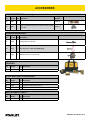
“T” CONNECTIONS (for pin brazing)
Item
No. Part No. Qty Description
Brazing Pin
Required
65 35857 1 Type C Copper Plate with M8 x 18 Brass Threaded Stud T-Bolt 35835 x2
66 35861 1 Type D Copper Plate with M16 x 32 Stainless Steel Threaded
Stud T-Bolt 35837 x4
GRINDER ABRASIVES
Item
No. Part No. Qty Description
67 73358 1 Carbide Burr (1/4” Shank)
68 35810 1 Grinding Wheel - NOT for SafeBonding!
69 73052 1 Bull Nose Stone, 2” (1/4” Shank)
GRINDER
Item
No. Part No. Qty Description
71 DCG426M2 1 Cordless Grinder Kit. Includes (2) Battery (1) Charger.
COLD WEATHER ACCESSORIES
Item
No. Part No. Qty Description
71 82788 1 Instant Hot Packs, 5” x 9”, 24 Pack
72 82789 1 Heat Pack, Body Warmer, 240 ct.
73 DHX165 1 Electric Heater, 120V
REPLACEMENT PARTS
Item
No. Part No. Qty Description
74 88916 1 Front Piece for SB4 & SB15 Brazing Guns
ACCESSORIES

16 ► EP30200 User Manual
CABLES
Item
No. Part No. Qty Description
82 35820 1 Extension Cable for Grinding
83 35819 1 Extension Cable for Ground
84 41768 1 Adapter, Charging
85 62214 1 Pigtail Charge Adapter
86 66266 1 Ground Clamp Assembly (Vise Grip Style)
ACCESSORIES
FUSES, CHARGERS & BATTERIES
Item
No. Part No. Qty Description
75 56557 1 Fuse, PCB EP30/60
76 56558 1 Fuse, Grinder Outlet EP30
77 56559 1 Fuse, Control Cable EP30
78 35866 1 Charger 36 VDC 7 AMP EP30/60 W/ Special DC plug.
79 84936 1 Inverter 1000 Watt
80 40409 1 Battery 16 AMP 12 Volt EP30
81 82877 1 EP30 Cart

EP30200 User Manual ◄ 17
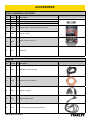
ACCESSORIES
GUNS
Item
No. Part No. Qty Description
91 BG10100 1 Pin Brazing Gun
92 BG10101 1 Angle Head Gun
93 35823 1 Plug Male Grinder 4-Pin
94 65831 1 Plug Male Controller Gun 3-Pin
95 66696 1 Plug Male Power Supply Gun Cable
96 66697 1 Plug Male Ground Cable
97 56556 1 Charger/Generator Plug
CABLES
Item
No. Part No. Qty Description
87 72999 1 Econnect Ground Magnet (Magnetic ground for econnect kit)
88 35818 1 Extension Cable for S4 Brazing Gun
89 35816 1 Standard Cable for S4 Pistol 2.7m/8.8ft
90 35817 1 Long Cable for S4, 4.5m/14.75ft

18 ► EP30200 User Manual
TOOLS
Item
No. Part No. Qty Description
98 37946 1 Hole Punch Tool 9.5mm
99 35824 1 Hole Punch Tool 8.0mm
100 62394 1 Lift Height Tool BG10100 Pin Braze Gun
ACCESSORIES

EP30200 User Manual ◄ 19
A
A
01
02
03
04
05
06
07
09
13
12
08
18
17
14
14
19
24
15
16
16
15
10
11
11
23
23
20
30
29
27
28
28
22
21
24
25
25
2526
26
25
26
25
31
26
25
25
26
29
30
25
31
30
30
29
29
32
32
33
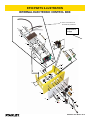
Electronic box for EP30 XC
34. Resistor & Circuit Board Unit
Assembled and precalibrated
INTERNAL ELECTRONIC CONTROL BOX
EP30 PARTS ILLUSTRATION
35 Includes all
components on
this page

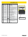
20 ► EP30200 User Manual
Item Part No. Qty Description
01 66838 1 FRAME EP30
02 66846 1 LABEL EP30
03 66839 1 CIRCUIT BOARD
04 66018 1 RELAY
05 66840 1 CIRCUIT BOARD MOUNTING PLATE
06 66841 1 RESISTOR MOUNTING PLATE
07 66698 1 SHUNT RESISTOR ASSY W/CABLE
08 66843 1 YELLOW LED LENS
09 66844 1 RED LED LENS
10 66694 1 KNOB FOR ROTARY SWITCH
11 66695 2 ROTARY SWITCH
12 66691 1 GRINDER RECEPTACLE
13 65830 1 GUN CONTROL RECEPTACLE
14 66847 1 FUSE BRACKET 5x20
15 66692 1 GUN POWER SUPPLY
RECEPTACLE
16 66693 1 GROUND RECEPTACLE
17 56558 1 FUSE FOR GRINDER 15A
18 56559 1 FUSE 1A
33 56557 1 GLASS FUSE FOR PCB
34 66845 1
RESISTOR & CIRCUIT BOARD UNIT
(As shown on previous page outlined by
black line).
35 66131 1
EP30 ELECTRONIC BOX
Complete unit as shown on previous
page.
36 35801 1 Battery Box
EP30 PARTS LIST
36 Battery Box Only (Lower
Black Box shown above).
Seite wird geladen ...
Seite wird geladen ...
Seite wird geladen ...
Seite wird geladen ...
-
 1
1
-
 2
2
-
 3
3
-
 4
4
-
 5
5
-
 6
6
-
 7
7
-
 8
8
-
 9
9
-
 10
10
-
 11
11
-
 12
12
-
 13
13
-
 14
14
-
 15
15
-
 16
16
-
 17
17
-
 18
18
-
 19
19
-
 20
20
-
 21
21
-
 22
22
-
 23
23
-
 24
24


in anderen Sprachen
- English: Stanley EP30200 User manual
Andere Dokumente
-
Stanley Black & Decker EP30 Benutzerhandbuch
-
-
Danfoss Electric expansion valve, type CCMT Installationsanleitung
-
-
GYS AUTOMOTIVE PLASTICS REPAIR KIT Bedienungsanleitung
-
Fischer [CF] EASY Benutzerhandbuch
-
-