
Model
Modèle
Modelo
Modell
1097
®
© 2021 Milescraft, Inc. • www.milescraft.com M1097MRV4 • 01/21
1
2 1 0 1 2
2
1
0
1
2
6 5 4 3 2 1 0 1 2 3 4 5 6
2
1
0
5
1
2
3
4
6
7
8
9
10
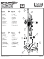
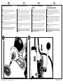
ToolStandMR
1 - Cuerpo principal
2 - Tubo de acero
3 - Base del ToolStandMR
4 - Perilla S
5 - M6x1mm Tuerca
6 - Soporte del cable
7 - M6x1x12mm Perno
8 - Tuercas de seguridad (2)
9 - Tornillos para madera #10 (4)
10 - Patas de goma (4)
ToolStand
1 - Gehäuse Oberteil
2 - Rundsäule
3 - Grundplatte
4 - S-förmige Griffschraube
5 - Mutter, M6 x 1mm
6 - Kabelführung
7 - Schraube, M6 x 1 x 12mm
8 - Spannzangenmutter (2)
9 - Flachkopfschraube, Holz (4)
10 - Gummifüße (4)
ToolStandMC
1 - Boîtier principal
2 - Tube d'acier
3 - Base du ToolStandMC
4 - Bouton en « S »
5 - M6x1mm Écrou
6 - Passe-fil
7 - M6x1x12mm Boulon
8 - Écrous de collet (2)
9 - Vis à bois n°10 (4)
10 - Pieds en caoutchouc (4)
ToolStand™
1 - Main Housing
2 - Steel Tube
3 - ToolStand™ Base
4 - S-Knob
5 - M6x1mm Nut
6 - Cord Holder
7 - M6x1x12mm Bolt
8 - Collet Nuts (2)
9 - #10 Wood Screws (4)
10 - Rubber Feet (4)
GB F
E D

Milescraft, Inc.
www.milescraft.com
2
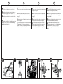
TABLE OF CONTENTS:
Overview............................................................ 1
Package Contents................................................3
Assembling the ToolStand™...........................4-5
Vertical Mounting of Main Housing.....................6
Horizontal Mounting of Main Housing..................7
Attaching your Rotary Tool............................... 8-9
Using the ToolStand™ in the
Vertical Mount Position..................................10
Hints.............................................................11
Using the ToolStand™ in the
Horizontal Mount Position.................................. 12
Replacement Parts.............................................13
TABLE DES MATIÈRES :
Vue d’ensemble....................................................1
Contenu du paquet...............................................3
Montage du ToolStandMC...................................4-5
Montage vertical du boîtier principal....................6
Montage horizontale du boîtier principal..............7
Installer votre outil rotatif................................8-9
Utiliser le ToolStandMC dans
la position de montage vertical........................10
Conseils....................................................... 11
Utiliser le ToolStandMC dans
la position de montage horizontale...............12
Pièces de rechange............................................13
TABLA DE CONTENIDO:
Visión de conjunto...............................................1
Contenido del paquete.........................................3
Armado del ToolStandMR................................... 4-5
Montaje vertical del cuerpo principal................... 6
Montaje horizontal del cuerpo principal...............7
Colocación de su herramienta rotativa..........8-9
Uso del ToolStandMR
en posición vertical...........................................10
Consejos...................................................... 11
Uso del ToolStandMR en
posición horizontal........................................12
Componentes de Repuesto................................13
INHALTSVERZEICHNIS:
Übersicht............................................................. 1
Verpackungsinhalt...............................................
3
Montage des ToolStand....................................4-5
Vertikale Montage des Gehäuse-Oberteils..........6
Horizontale Montage des Gehäuse-Oberteils.......7
Montage Ihres Multifunktionswerkzeugs.......8-9
Anwendung des ToolStand
in vertikaler Montageposition...........................10
Hinweise............................................................ 11
Anwendung des ToolStand in
horizontaler Montageposition.............................12
Ersatzteile......................................................... 13
GB F E D

© 2021 Milescraft, Inc. • www.milescraft.com M1097MRV4 • 01/21
3
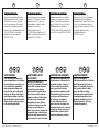
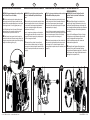
PACKAGE CONTENTS:
Unpack all items and check with Figure 1
and “Replacement Parts table” (see page
13). Make sure all items are accounted
for before discarding any of the packing
material. For any missing parts, contact
Customer Service at [email protected] or
1-224-227-6930 in U.S. and Canada.
Outside of the U.S and Canada dial
001-224-227-6930.
CONTENU DU PAQUET :
Inspectez chaque pièce en vous aidant
de la Figure 1 et du tableau «Pièces de
rechange» (voir page 13). En cas de
pièce manquante, contactez le service
d’assistance à la clientèle à
info@ milescraft.com ou au
1-224-227-6930 aux États-Unis et au
Canada. L'extérieur des États-Unis et du
Canada 001-224-227-6930.
CONTENIDO DEL PAQUETE:
Compruebe cada artículo con la Figura 1
y la tabla de “Piezas sueltas” (consulte la
página 13). Para obtener cualquier pieza
que falte, contacte a Servicio al Cliente en
[email protected] o llamando al
1-224-227-6930 en EE.UU. y Canadá. Fuera
de los EE.UU. y Canadá 001-224-227-6930.
PACKUNGSINHALT:
Entnehmen Sie alle Teile der Verpackung
und überprüfen Sie die Vollständigkeit
anhand Zeichnung 1 und der Teileliste (Seite
13), ehe Sie die Verpackung entsorgen.
Sollten Teile fehlen, so melden Sie sich bitte
bei unserem Kunden dienst unter
[email protected] oder
001-224-227-6930.
SAFETY WARNING:
Read, understand, and follow your
power tool manufacturer’s instructions
for safety. Always wear safety glasses
or eye shields before commencing
power tool operation. Always keep
hands, face, hair, loose clothing, and
body at a safe distance from spindles
and cutting tools. Always keep a firm
grip on tool handles when in operation.
Always disconnect from power source
before adjusting power tools.
AVERTISSEMENT RELATIF
À LA SÉCURITÉ :
Vous devez lire, comprendre et
respecter les instructions du fabricant
de votre outil électrique concernant
la sécurité. Vous devez toujours
porter des lunettes de protection ou
des protecteurs oculaires avant de
commencer à utiliser l’outil électrique.
Vos mains, visage et corps doivent
constamment être à une distance
sécuritaire des broches et des outils
de coupe. Lorsque l’outil est en
marche, assurez-vous de toujours tenir
fermement la poignée. Avant d’ajuster
un outil électrique, assurez-vous qu’il
est débranché de sa source de courant.
ADVERTENCIA DE SEGURIDAD:
Por seguridad lea, comprenda y siga
las instrucciones del fabricante de su
herramienta eléctrica. Siempre use
lentes de seguridad o protecciones
para los ojos antes de iniciar la
operación de la herramienta eléctrica.
Siempre mantenga las manos, la cara
y el cuerpo a una distancia segura
de los vástagos y herramientas
de corte. Siempre mantenga un
agarre firme sobre los mangos de la
herramienta cuando ésta se encuentre
en operación. Siempre desconecte la
alimentación de corriente antes de
ajustar las herramientas eléctricas.
SICHERHEITSHINWEIS:
Folgen Sie unbedingt den
Sicherheitsvorschriften des Herstellers
Ihres Elektrowerkzeuges. Tragen Sie
immer eine Schutzbrille oder anderen
Gesichtsschutz. Halten Sie Hände,
Gesicht und Körper in sicherer
Entfernung von drehenden Teilen und
Schneidwerkzeugen. Halten Sie die
Handgriffe beim Arbeiten stets fest.
Ziehen Sie immer den Stecker vor
jedem Werkzeugwechsel.
GB F E D

© 2021 Milescraft, Inc. • www.milescraft.com M1097MRV4 • 01/21
4
2 1 0 1 2
2
1
0
1
6 5 4 3 2 1 0 1 2 3 4 5 6
0 1 2
6
5
4
3
2
1
0
1
2
3
4
5
6
5 4 3 2 1 0 1 2 3 4 5 6
5522113344
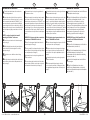
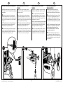
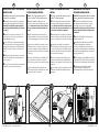
1 Turn the base upside down so the scales on the
base are facing downward.
2 Insert each rubber foot into the four screw holes
found at each corner of the base (see img. 1) or, using
the four screws included with the ToolStand™ , you
can mount the unit to any work surface by drilling the
screws through the four holes on the base (see img. 2).
Clamps can also be used to secure the unit in place. Be
sure the clamps are tightly secured and are not in the
way.
NOTE: Do not have the rubber feet inserted if
mounting the ToolStand™ with screws.
3 Place the hex nut into the slot of the tube support
hole (see img. 3).
4 While holding the hex nut in place, insert the base
bolt into the back of the tube support. Do not fully
tighten (see img. 4).
5 Flip the base over so that the scales are facing
upward.
6 On a flat surface, insert the steel tube into the tube
support. Be sure the steel tube is fully seated into the
base (see img. 5).
ASSEMBLING THE TOOLSTAND™
1 Retournez la base de sorte que les gabarits sur la
base pointent vers le bas.
2 Insérez chaque pied en caoutchouc dans les quatre
trous à chaque coin de la base (voir l'image 1) ou, en
utilisant les quatre vis fournies avec le ToolStandMC, vous
pouvez monter l’appareil sur n’importe quelle surface de
travail en insérant les vis à travers les quatre trous de la
base (voir l'image 2). Les colliers de serrage permettent
également de fixer l’unité en place. Veillez à ce que les
pinces soient bien serrées et qu’elles n’encombrent pas
l’espace.
REMARQUE : N’insérez pas les pieds en caoutchouc
si vous montez le ToolStandMC avec des vis.
3 Placez l’écrou hexagonal dans la fente du trou du
support de tuyau (voir l'image 3).
4 Tout en gardant l’écrou hexagonal en place, insérez
le boulon de base à l’arrière du support de tuyau. Ne pas
serrer complètement (voir l'image 4).
5 Retournez la base de sorte que les gabarits soient
orientés vers le haut.
6 Sur une surface plane, insérez le tube d’acier dans
le support de tube. Veillez à ce que le tube en acier soit
correctement inséré dans la base (voir l'image 5).
1 Dé vuelta la base de modo que las reglas de la base
queden apuntando hacia abajo.
2 Inserte cada una de las patas de goma en los cuatro
orificios que están en las esquinas de la base (ver la
imagen 1), o puede fijar la unidad a cualquier superficie
de trabajo con los cuatro tornillos que vienen incluidos
con el ToolStandMR, colocando los tornillos a través de
los cuatro orificios de la base (ver la imagen 2). También
puede utilizar abrazaderas para asegurar la unidad en
su lugar. Asegúrese de que las abrazaderas estén bien
apretadas y que no interfieran.
NOTA: No deje las patas de goma colocadas si va a
montar el ToolStandMR con tornillos.
3 Coloque la tuerca hexagonal en la ranura del orificio
de soporte para el tubo (ver la imagen 3).
4 Mientras sostiene la tuerca hexagonal en su lugar,
inserte el perno de la base por la parte posterior del
soporte del tubo. No lo ajuste completamente (ver la
imagen 4).
5 Dé vuelta la base de modo que las reglas queden
apuntando hacia arriba.
6 Sobre una superficie plana, inserte el tubo de
acero en el soporte para el tubo. Verifique que el tubo
esté completamente apoyado dentro de la base (ver la
imagen 5).
1 Drehen Sie die Grundplatte um, damit die Skalen an
der Grundplatte nach unten zeigen.
2 Setzen Sie die Gummifüße in die vier Schraublöcher
an den Ecken der Grundplatte (siehe Abb. 1) oder
verwenden Sie die vier Schrauben, die mit dem
ToolStand mitgeliefert wurden (siehe Abb. 2). Sie
können das Teil auf jede Arbeitsfläche montieren, indem
Sie die Schrauben in die vier Löcher der Grundplatte
bohren. Das Gerät kann aber auch mit Klemmen
befestigt werden. Vergewissern Sie sich, dass die
Klemmen gut gesichert und nicht im Weg sind.
ANMERKUNG: Bringen Sie die Gummifüße nicht
an, wenn Sie den ToolStand mit Schrauben
festmontieren.
3 Stecken Sie die Sechskantmutter in den Schlitz des
Rundsäulenstutzlochs (siehe Abb. 3).
4 Fügen Sie den Grundplattenbolzen in die Rückseite
des Rundsäulenstutzens ein, während Sie die
Sechskantmutter in Position halten. Nicht vollständig
festziehen (siehe Abb. 4).
5 Drehen Sie die Grundplatte um, damit die Skalen
nach oben zeigen.
6 Fügen Sie die Rundsäule auf einer ebenen
Oberfläche in die Rundsäulenstütze ein. Achten Sie
darauf, dass die Rundsäule komplett in der Grundplatte
sitzt (siehe Abb. 5).
MONTAGE DU TOOLSTANDMC ARMADO DEL TOOLSTANDMR MONTAGE DES TOOLSTAND
GB F E D

© 2021 Milescraft, Inc. • www.milescraft.com M1097MRV4 • 01/21
5
6 5 4 3 2 1 0 1
2
1
2
1
0
66778899bkbk
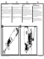
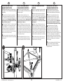
7 Using a 3/8" (9.5mm) wrench, firmly tighten the
base bolt to secure the tube in place (see img. 6).
8 Insert the cord holder into the top of the tube, with
the three prongs going into the tube (see img. 7).
9 Insert the s-knob into the hole near the tool holder
(see img. 8).
bk The main housing can be mounted either
horizontally or vertically. See " Vertical Mounting of Main
Housing" (see img. 9) and/or "Horizontal Mounting of
Main Housing" (see img. 10).
ASSEMBLING THE TOOLSTAND™
7 À l’aide d’une clé de 9,5 mm (3/8 po), serrez le
boulon de base pour fixer le tube en place (voir l'image
6).
8 Insérez le passe-fil dans la partie supérieure du
tube, avec les trois broches insérées dans le tube (voir
l'image 7).
9 Insérez le bouton en « S » dans le trou près du porte-
outil (voir l'image 8).
bk Le boîtier principal peut être monté horizontalement
ou verticalement. Voir « Montage vertical du boîtier
principal » (voir l'image 9) ou « Montage horizontal du
boîtier principal » (voir l'image 10).
7 Con una llave de 9,5 mm (3/8 pulgada), apriete
firmemente el perno de la base para asegurar el tubo en
su lugar (ver la imagen 6).
8 Inserte el soporte para el cable en la parte superior
del tubo, con las tres patas hacia adentro del tubo (ver
la imagen 7).
9 Inserte la perilla S dentro del orificio que está cerca
del soporte para la herramienta (ver la imagen 8).
bk El cuerpo principal se puede montar de forma
horizontal o vertical. Consulte "Montaje vertical del
cuerpo principal" (ver la imagen 9) y/o "Montaje
horizontal del cuerpo principal" (ver la imagen 10).
7 Ziehen Sie den Grundplattenbolzen mit einem
9,5mm (3/8 Zoll) Schraubenschlüssel fest an, damit die
Rundsäule sicher befestigt ist (siehe Abb. 6).
8 Stecken Sie die Kabelführung oben in die Rundsäule
ein, wobei die drei Zacken in die Rundsäule eingefügt
werden (siehe Abb. 7).
9 Stecken Sie die S-förmige Griffschraube in das Loch
neben der Machinenaufnahme (siehe Abb. 8).
bk Das Gehäuse-Oberteil kann entweder horizontal
oder vertikal montiert werden. Siehe „ Vertikale Montage
des Gehäuse-Oberteils” (siehe Abb. 9) und/oder
„ Horizontale Montage des Gehäuse-Oberteils” (siehe
Abb. 10).
MONTAGE DU TOOLSTANDMC ARMADO DEL TOOLSTANDMR MONTAGE DES TOOLSTAND
GB F E D

© 2021 Milescraft, Inc. • www.milescraft.com M1097MRV4 • 01/21
6
2
1
0
112a 2b
NOTE: With the main housing in the vertical position
the ToolStand™ is used for drilling.
1 With the main housing in the vertical position, insert
the triangular knob into the hole on the side of the tube
holder and then screw the additional hex nut onto the bolt
of the triangular knob. Do not fully tighten (see img. 1).
Hint: The plastic cap found on the end of the triangular
knob may have to be removed to get the hex nut on.
Reinsert the plastic cap after the hex nut is on.
2 Slide the main housing over the tube, through the
vertical slot at the back of the main housing (see img. 2a).
Using the triangular knob, tighten the main housing at any
height for the time being (see img. 2b).
VERTICAL MOUNTING OF MAIN HOUSING
REMARQUE : Avec le boîtier principal en position
verticale, le ToolStandMC peut être utilisé pour
percer.
1 Avec le boîtier principal en position verticale, insérez
le bouton triangulaire dans le trou sur le côté du support
de tube et vissez l’écrou hexagonal supplémentaire
sur le boulon du bouton triangulaire. Ne pas serrer
complètement (voir l'image 1).
Conseil : Le capuchon en plastique sur l’extrémité du
bouton triangulaire peut être retiré pour monter l’écrou
hexagonal. Réinsérez le capuchon en plastique après
que l’écrou hexagonal est installé.
2 Glissez le boîtier sur le tube, à travers la fente
verticale à l’arrière du boîtier principal (voir l'image 2a).
En appuyant sur le bouton triangulaire, serrez le boîtier
principal à n’importe quelle hauteur pour le moment (voir
l'image 2b).
NOTA: Con el cuerpo principal en posición vertical, el
ToolStandMR se utiliza para perforarr.
1 Con el cuerpo principal en posición vertical, inserte
la perilla triangular en el oricio del costado del soporte
para el tubo y luego enrosque la tuerca hexagonal
adicional en el perno de la perilla triangular. No la ajuste
completamente (ver la imagen 1).
Consejo: Puede ser necesario remover la tapa plástica
que viene en el extremo de la perilla triangular para poder
colocar la tuerca hexagonal. Vuelva a colocar la tapa
plástica luego de colocar la tuerca hexagonal.
2 Deslice el cuerpo principal por el tubo, a través de la
ranura vertical de la parte posterior del cuerpo principal
(ver la imagen 2a). Con la perilla triangular, ajuste el
cuerpo principal a cualquier altura por el momento (ver la
imagen 2b).
ANMERKUNG: Wenn das Gehäuse-Oberteil in
vertikaler Position ist, wird der ToolStand zum
Bohren benutzt.
1 Mit dem Gehäuse-Oberteil in vertikaler Position,
stecken Sie die 3-eckige Griffschraube in das Loch an
der Seite der Rundsäulenhalterung und schrauben Sie
dann die zusätzliche Sechskantmutter an den Bolzen der
3-eckingen Griffschraube. Nicht vollständig festziehen
(siehe Abb.1).
Hinweis: Die Kunststoffkappe am Ende der 3-eckigen
Griffschraube muss möglicherweise entfernt werden,
um die Sechskantmutter anzubringen. Setzen
Sie die Kunststoffklappe wieder auf, nachdem die
Sechskantmutter angebracht ist.
2 Schieben Sie das Gehäuse-Oberteil durch den
vertikalen Schlitz an der Rückseite des Gehäuse-
Oberteils über die Rundsäule (siehe Abb. 2a). Ziehen Sie
das Gehäuse mit der 3-eckigen Griffschraube vorerst in
beliebiger Höhe fest (siehe Abb. 2b).
MONTAGE VERTICAL DU BOÎTIER PRINCIPAL MONTAJE VERTICAL DEL CUERPO PRINCIPAL VERTIKALE MONTAGE DES
GEHÄUSE-OBERTEILS
GB F E D

© 2021 Milescraft, Inc. • www.milescraft.com M1097MRV4 • 01/21
7
1
2
1
112a 2b
NOTE: With the main housing in the horizontal position
the ToolStand™ is used for sanding, brushing, grinding,
and polishing.
1 With the main housing in the horizontal position,
insert the triangular knob into the hole at the base of
the main housing and then screw the additional hex nut
onto the bolt of the triangular knob. Do not fully tighten
(see img. 1).
HINT: The plastic cap found on the end of the triangular
knob may have to be removed to get the hex nut on.
Reinsert the plastic cap after the hex nut is on.
2 Slide the main housing over the tube, through the
hole at the base of the main housing (see img. 2a).
Using the triangular knob, tighten the main housing at
any height for the time being (see img. 2b).
HORIZONTAL MOUNTING OF MAIN HOUSING
REMARQUE : Avec le boîtier principal en position
horizontale, le ToolStandMC peut être utilisé pour poncer,
brosser, meuler et polir.
1 Avec le boîtier principal en position horizontale,
insérez le bouton triangulaire dans le trou à la base
du boîtier principal et ensuite vissez l’écrou hexagonal
supplémentaire sur le boulon du bouton triangulaire. Ne
pas serrer complètement (voir l'image 1).
HINT: The plastic cap found on the end of the triangular
knob may have to be removed to get the hex nut on.
Reinsert the plastic cap after the hex nut is on.
2 Glissez le boîtier sur le tube, dans le trou à la base
du boîtier principal (voir l'image 2a). En appuyant sur le
bouton triangulaire, serrez le boîtier principal à n’importe
quelle hauteur pour le moment (voir l'image 2b).
NOTA: Con el cuerpo principal en posición horizontal, el
ToolStandMR se utiliza para lijar, cepillar, fresar y pulir.
1 Con el cuerpo principal en posición horizontal,
inserte la perilla triangular en el orificio de la base del
cuerpo principal y luego enrosque la tuerca hexagonal
adicional en el perno de la perilla triangular. No la ajuste
completamente (ver imagen 1).
CONSEJO: Puede ser necesario remover la tapa plástica
que viene en el extremo de la perilla triangular para poder
colocar la tuerca hexagonal. Vuelva a colocar la tapa
plástica luego de colocar la tuerca hexagonal.
2 Deslice el cuerpo principal por el tubo, a través del
orificio de la base del cuerpo principal (ver imagen 2a).
Con la perilla triangular, ajuste el cuerpo principal a
cualquier altura por el momento (ver la imagen 2b).
ANMERKUNG: Wenn das Gehäuse-Oberteil in
horizontaler Position ist, wird der ToolStand zum
Schleifen, Entrosten, Entgraten und Polieren benutzt.
1 Mit dem Gehäuse-Oberteil in horizontaler Position,
stecken Sie die 3-eckige Griffschraube in das Loch
der Grundplatte des Gehäuse-Oberteils und drehen
Sie die Sechskantmutter an den Bolzen der 3-eckigen
Griffschraube. Nicht vollständig festziehen (siehe Abb.
1).
HINWEIS: Die Kunststoffkappe am Ende der 3-eckigen
Griffschraube muss möglicherweise entfernt werden,
um die Sechskantmutter anzubringen. Setzen
Sie die Kunststoffklappe wieder auf, nachdem die
Sechskantmutter angebracht ist.
2 Schieben Sie das Gehäuse-Oberteil durch das
Loch der Grundplatte des Gehäuse-Oberteils über die
Rundsäule (siehe Abb. 2a). Ziehen Sie das Gehäuse mit
der 3-eckigen Griffschraube vorerst in beliebiger Höhe
fest (siehe Abb. 2b).
MONTAGE HORIZONTALE DU BOÎTIER
PRINCIPAL
MONTAJE HORIZONTAL DEL CUERPO
PRINCIPAL
HORIZONTALE MONTAGE DES
GEHÄUSE-OBERTEILS
GB F E D

© 2021 Milescraft, Inc. • www.milescraft.com M1097MRV4 • 01/21
8
2
1
0
1122
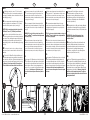
1 Remove the nose cap, that came with the rotary
tool, from the tip of the tool (see img. 1).
2 Place the rotary tool into the metal tool holder on the
main housing, with the tip of the tool going through the
hole on the metal tool holder. Be sure that the On/Off,
speed, and lock buttons/switches are accessible and
that the rotary tool is sitting straight in the tool holder
(see img. 2).
3 The ToolStand™ comes with two different collet
nuts. Determine which collet nut threads onto your
rotary tool.
ATTACHING YOUR ROTARY TOOL
1 Enlevez le capuchon qui accompagne l’outil rotatif
de l’extrémité de l’outil (voir l'image 1).
2 Placez l’outil rotatif du porte-outil métallique sur le
boîtier principal, avec la pointe de l’outil dans le trou
du porte-outil. Assurez-vous que les commutateurs de
marche/arrêt, vitesse et verrouillage soient accessibles
et que l’outil rotatif est tout droit dans le porte-outil (voir
l'image 2).
3 The ToolStandMC est livré avec deux écrous de collet
différents. Déterminez quel écrou de collet correspond à
votre outil rotatif.
1 Remueva la tapa que viene en la punta de la
herramienta rotativa (ver la imagen 1).
2 Coloque la herramienta rotativa en el soporte
metálico para la herramienta del cuerpo principal, con
la punta de la herramienta pasando a través del orificio
de la misma. Verifique que las llaves/controles de
encendido/apagado, velocidad y traba sean accesibles y
que la herramienta rotativa esté colocada derecha en el
soporte (ver la imagen 2).
3 El ToolStandMR viene con dos tuercas de seguridad
diferentes. Determine cuál de las tuercas de seguridad
se puede enroscar en su herramienta rotativa.
1 Entfernen Sie die aufgeschraubte Abdeckung
am vorderen Ende Ihres Multifunktionswerkzeugs
(Fräsgerät). (siehe Abb. 1).
2 Setzen Sie das Fräsgerät so in die
Maschinenaufnahme aus Metall, daß das vordere
Ende des Fräsgerätes durch das Loch in der Aufnahme
gesteckt wird. Achten Sie darauf, daß die Ein- / Aus- /
Drehzahl- und Verriegelungsknöpfe oder Schalter
zugänglich sind und daß das Fräsgerät senkrecht in der
Aufnahme sitzt (siehe Abb. 2).
3 Der ToolStand wird mit zwei verschiedenen
Spannzangenmuttern geliefert. Ermitteln Sie, welche
Spannzangenmutter auf Ihr Fräsgerät aufgeschraubt
werden kann.
INSTALLER VOTRE OUTIL ROTATIF COLOCACIÓN DE SU HERRAMIENTA
ROTATIVA
MONTAGE IHRES
MULTIFUNKTIONSWERKZEUGS
GB F E D

© 2021 Milescraft, Inc. • www.milescraft.com M1097MRV4 • 01/21
9
2
1
0
3344
4 Thread the collet nut onto the tip of the tool to
secure the rotary tool to the metal tool holder on the
main housing (see img. 3).
5 Insert the cord into the cord holder. Be sure that the
cord is clear from the work area. Make sure the cord
has enough slack to keep it from being pulled taut when
plunging your rotary tool (see img. 4).
6 Attach the desired rotary tool accessory to the rotary
tool. Follow the manufacturer's instructions for attaching
accessories to the rotary tool.
NOTE: The rotary tool accessory can be installed
before or after it is seated in the tool holder.
ATTACHING YOUR ROTARY TOOL
4 Vissez l’écrou du collet sur la pointe de l’outil
pour maintenir l’outil rotatif en place sur le porte-outil
métallique sur le boîtier principal (voir l'image 3).
5 Insérez le câble dans le porte-fils. Assurez-vous que
le cordon n’obstrue pas l’aire de travail. Assurez-vous
que le cordon ait suffisamment de mou pour éviter qu’il
ne soit tendu lorsque vous faites avancer votre outil
rotatif (voir l'image 4).
6 Fixez l’accessoire désiré sur l’outil rotatif. Suivez les
instructions du fabricant pour la fixation des accessoires
sur l’outil rotatif.
REMARQUE : L’accessoire de l’outil rotatif peut
être installé avant ou après qu’il est placé dans le
porte-outil.
4 Enrosque la tuerca de seguridad en la punta de la
herramienta para asegurar la herramienta rotativa al
soporte metálico del cuerpo principal (ver la imagen 3).
5 Inserte el cable dentro del soporte para cable.
Verifique que el cable esté alejado del área de trabajo.
Verifique que el cable esté lo suficientemente suelto
como para que no se tire de él al hacer descender la
herramienta rotativa (ver la imagen 4).
6 Coloque el accesorio deseado en la herramienta
rotativa. Siga las instrucciones del fabricante para
colocar accesorios en la herramienta rotativa.
NOTA: El accesorio para la herramienta rotativa
se puede instalar antes o después de colocar la
herramienta en el soporte.
4 Schrauben Sie die Spannzangenmutter auf das
Gewinde des Fräsgerätes, um es sicher mit der
Maschinenaufnahme (Metall) des Gehäuseoberteils zu
befestigen (siehe Abb. 3).
5 Stecken Sie das Kabel in die Kabelführung. Achten
Sie darauf, dass das Kabel nicht Ihren Arbeitsbereich
hindert. Vergewissern Sie sich, dass das Kabel
genug Spielraum hat, damit es beim Eintauchen des
Fräsgerätes (siehe Abb. 4).
6 Spannen Sie das gewünschte Zubehör in der
Spannzange fest.
ANMERKUNG: Das Zubehör kann sowohl vor als
auch nach dem Einbau in der Maschinenaufnahme
eingespannt werden.
INSTALLER VOTRE OUTIL ROTATIF COLOCACIÓN DE SU HERRAMIENTA
ROTATIVA
MONTAGE IHRES
MULTIFUNKTIONSWERKZEUGS
GB F E D

© 2021 Milescraft, Inc. • www.milescraft.com M1097MRV4 • 01/21
10
2 1 0 1 2
5 4 3 2 1 0 1 2 3 4 5 6
0 1 2
3
2
1
0
1
2
3
4
5
6
5 4 3 2 1 0 1 2 3 4 5 6
2
1
0
2
1
0
22441133
NOTE: With the main housing in the vertical position the
ToolStand™ is used for drilling.
1 Determine the desired height for your application
and then tighten the triangular knob to keep in place.
Warning: Do not tighten the head housing on the
tube any higher than flush with the top of the tube
(see img. 1).
2 Mark the hole locations on the work piece. The
scales on the base can be used to get precise hole
location markings (see img. 2).
3 Secure the work piece to the base before drilling
to prevent the work piece from climbing the drill bit or
spinning. Hold down clamps or a small utility vise (not
included) can be used to secure the work piece (see
img. 3).
4 With the bit touching the workpiece, adjust depth
stop to desired setting on the scale and tighten lock
screw (see img. 4).
5 You are now ready to drill. Follow the manufacturer's
instruction for use and safety of the rotary tool.
USING THE TOOLSTAND™ IN THE VERTICAL
MOUNT POSITION
REMARQUE : Avec le boîtier principal en position
verticale, le ToolStandMC peut être utilisé pour percer.
1 Déterminez la hauteur souhaitée pour votre
application et serrez le bouton triangulaire pour le fixer
en place. Avertissement : Ne pas serrer le boîtier de
la tête sur le tube au-dessus du haut du tube (voir
l'image 1).
2 Marquez l’emplacement des trous sur la pièce à
travailler. Les gabarits sur la base peuvent être utilisés
pour obtenir des marquages de trou précis (voir l'image
2).
3 Fixer la pièce à travailler sur la base avant de percer,
pour empêcher la pièce de monter sur la mèche ou de
tourner. Des serre-joints ou un petit étau utilitaire (non
inclus) peuvent être utilisés pour fixer la pièce à travailler
(voir l'image 3).
4 Avec la mèche touchant la pièce à travailler, réglez
la jauge de profondeur comme désiré en réglant le
collier d’arrêt et en serrant la vis de blocage (voir l'image
4).
5 Vous êtes maintenant prêt(e) à faire griller votre
repas. Suivez les instructions du fabricant pour le mode
d’emploi et la sécurité de l’outil rotatif.
NOTA: Con el cuerpo principal en posición vertical, el
ToolStandMR se utiliza para perforar.
1 Determine la altura deseada para su aplicación y
luego apriete la perilla triangular para mantenerla en
su lugar. Advertencia: No apriete el cuerpo principal
sobre el tubo más alto que cuando queda al ras con
la parte superior del tubo (ver la imagen 1).
2 Marque la ubicación de los agujeros en la pieza de
trabajo. Puede utilizar las reglas de la base para marcar
la ubicación de los agujeros con precisión (ver la imagen
2).
3 Asegure la pieza de trabajo a la base antes de
perforar para evitar que la pieza de trabajo se trepe a la
broca o que comience a girar. Puede utilizar pequeñas
abrazaderas o una prensa (no incluida) para asegurar la
pieza de trabajo (ver la imagen 3).
4 Con la broca tocando la pieza de trabajo, ajuste
el medidor de profundidad a la profundidad deseada
deslizando el tope y apretando el tornillo de fijación (ver
la imagen 4).
5 Ahora está listo para perforar. Siga las instrucciones
del fabricante para utilizar la herramienta rotativa de
forma segura.
ANMERKUNG: Wenn das Gehäuse-Oberteil in vertikaler
Position ist, wird der ToolStand zum Bohren benutzt.
1 Ermitteln Sie die gewünschte Höhe für Ihren
Anwendungszweck und ziehen Sie die 3-eckige
Griffschraube gut an, damit sie sicher festsitzt.
Warnung: Das Gehäuseoberteil darf nicht höher als
am oberen Ende der Rundsäule befestigt werden
(siehe Abb. 1).
2 Markieren Sie die Mitte der Bohrung auf dem
Werkstück (siehe Abb. 2).
3 Befestigen Sie das Werkstück vor dem Bohren
sicher auf der Grundplatte, um das Anheben
oder Rotieren des Werkstücks zu vermeiden. Die
Verwendung von Schraubzwingen oder einem kleinen
Schraubstock (nicht mitgeliefert) kann einen sicheren
Halt bieten (siehe Abb. 3).
4 Mit der Bohrspitze auf dem Werkstück, stellen Sie
die gewünschte Tiefe mittels Tiefenstopp auf der Skala
ein. Ziehen Sie die Feststellschraube an (siehe Abb. 4).
5 Sie können nun mit dem Bohren anfangen.
Folgen Sie unbedingt den Gebrauchs- und
Sicherheitsanweisungen des Fräsgeräteherstellers.
UTILISER LE TOOLSTANDMC DANS LA
POSITION DE MONTAGE VERTICAL
USO DEL TOOLSTANDMR EN POSICIÓN
VERTICAL
ANWENDUNG DES TOOLSTAND IN
VERTIKALER MONTAGEPOSITION
GB F E D

© 2021 Milescraft, Inc. • www.milescraft.com M1097MRV4 • 01/21
11
2
1
0
6
5
4
5 4 3 2 1 0 1 2 3 4 5 6
2
1
0
6
5 4 3 2 1 0 1 2 3 4 5 6
0 1 2
1/4” (6.35mm) Gap
112244
3a 3b
1 If drilling a round piece, use a " V" block or vise to
keep the object in place. A center punch mark may be
necessary for materials such as a metal tube before you
start drilling (see img. 1).
2 It is recommended to adjust the height of the main
housing so that there is a maximum of 1/4" (6.5mm)
between drill bit tip and work piece (see img. 2).
NOTE: With the main housing locked in placed, the
ToolStand™ has a 2.5" (63.5mm) travel distance.
3 Do not force feed the drill bit into the work piece.
The motor speed should never be noticeably reduced for
any reason. Feed carefully when approaching the point
of breakthrough. Use multiple up and down motions
when drilling to allow for smooth breakthrough (see img.
3a & 3b).
4 The rotary tool can be cord or cordless, as long as
the nose cap can be removed and the collet nut can be
attached.
5 To store the ToolStand™ with the bit still inserted,
move the main housing down until the bit is partially in
the center hole of the base. Tighten the triangular knob
and s-knob to keep the main housing in place (see img.
4). Warning: Do not lower the bit all the way down.
The bit should not be ush with the feet of the base.
HINTS
1 Si vous percez une pièce ronde, utilisez une cale
en « V » ou un étau pour garder l’objet en place. Une
marque de poinçon peut être nécessaire pour les
matériaux comme un tube de métal avant de procéder
au perçage (voir l'image 1).
2 Il est recommandé d’ajuster la hauteur du boîtier
principal afin qu’il y ait un maximum de 6,5mm (1/4 po)
entre la pointe de la mèche et la pièce à travailler (voir
l'image 2).
REMARQUE : Avec le boîtier principal verrouillé en
place, le ToolStandMC a une distance de déplacement
de 63,5 mm (2,5 po).
3 Ne pas faire avancer la perceuse dans la pièce
à travailler. La vitesse du moteur ne doit jamais être
réduite sensiblement pour une raison quelconque. Faire
avancer avec soin lorsque vous approchez le point
de percée. Faites monter et descendre la perceuse
plusieurs fois pour une percée nette (voir l'image 3a et
3b).
4 X
5 Pour ranger le ToolStandMC avec la mèche toujours
insérée, déplacez le boîtier principal vers le bas jusqu'à
ce que la mèche soit partiellement insérée dans le trou
central de la base. Serrez le bouton triangulaire et le
bouton en « S » pour garder le boîtier principal en place
(voir l'image 4). Avertissement : N’abaissez pas la
mèche. La mèche ne doit pas afeurer les pieds de
la base.
1 Si tiene que perforar una pieza redonda, utilice un
bloque o prensa en "V" para mantener el objeto en su
lugar. Podría ser necesario hacer una marca con un
punzón en materiales como un tubo metálico antes de
comenzar a perforar (ver la imagen 1).
2 Le recomendamos ajustar la altura del cuerpo
principal de modo que quede un máximo de 6,5 mm
(1/4 pulgada) entre la punta de la broca y la pieza de
trabajo (ver la imagen 2).
NOTA: Con el cuerpo principal trabado en su lugar, el
ToolStandMR tiene una distancia de desplazamiento
de 63,5 mm (2,5 pulgada).
3 No fuerce la broca dentro de la pieza de trabajo. La
velocidad del motor no debe reducirse notablemente por
ningún motivo. Avance cuidadosamente cuando esté por
atravesar la pieza de trabajo. Utilice varios movimientos
hacia arriba y hacia abajo al perforar para atravesar la
pieza suavemente (ver la imagen 3a y 3b).
4 X
5 Para guardar el ToolStandMR con la broca colocada,
mueva el cuerpo principal hacia abajo hasta que la
broca esté parcialmente dentro del orificio central de
la base. Apriete la perilla triangular y la perilla S para
mantener al cuerpo principal en su lugar (ver la imagen
4). Advertencia: No descienda completamente la
broca. La broca no debe quedar al ras con las patas
de la base.
1 Verwenden Sie beim Bohren eines runden
Werkstücks entweder ein Prisma oder einen
Schraubstock, um das Werkobjekt zu befestigen.
Eine Markierung mit Körner ist möglicherweise vor
dem Bohren von Materialien wie einem Metallrohr
erforderlich (siehe Abb. 1).
2 Es empfiehlt sich, die Höhe des Gehäuse-Oberteils
so einzustellen, daß zwischen Bohrer und Werkstück
ein Abstand von maximal 6,5mm (1/4 Zoll) bleibt (siehe
Abb. 2).
ANMERKUNG: Ist das Gehäuseoberteil starr
verriegelt, so beträgt die Gesamtdistanz des
Vorschubs 63mm.
3 Drücken Sie den Bohrer nicht mit Gewalt in das
Werkstück. Die Motordrehzahl sollte niemals aus
irgendwelchen Gründen merklich reduziert werden.
Durch mehrere Auf- und Abwärtsbewegungen
beim Bohren, ermöglichen Sie einen reibungslosen
Durchbruch (siehe Abb. 3a und 3b).
4 X
5 Um den ToolStand mit eingespanntem Bohrer zu
lagern, senken Sie das Gehäuse-Oberteil herunter, bis
sich der Bohrer teilweise im Mittelloch der Grundplatte
befindet. Ziehen Sie die 3-eckige und S-förmige
Griffschraube fest an, um das Gehäuse-Oberteil sicher
aufzubewahren (siehe Abb. 4). Warnung: Senken Sie
den Bohrer nicht komplett nach unten. Der Bohrer
sollte sich nicht auf gleicher Höhe mit den Füßen der
Grundplatte benden.
CONSEILS CONSEJOS HINWEISE
GB F E D

© 2021 Milescraft, Inc. • www.milescraft.com M1097MRV4 • 01/21
12
1 0 1 2
6
5
4
3
2
1
0
1
2
3
4
5
6
5 4 3 2 1 0 1 2 3 4 5 6
1122
NOTE: With the main housing in the horizontal position
the ToolStand™ is used for sanding, brushing, grinding,
and polishing.
1 Determine the desired height for your application
and then tighten the triangular knob to keep in place.
It is recommended to have the main housing as close
to the base as possible. Warning: Do not tighten the
head housing on the tube any higher than flush with
the top of the tube (see img. 1).
2 Be sure that the ToolStand™ is on a flat, level work
surface. Using the four screws and washers included
with the ToolStand™ , you can mount the unit to any
work surface by driving the screws through the four
holes on the base (see img. 2). Clamps can also be
used to secure the unit in place. Be sure the clamps are
tightly secured and are not in the way.
3 You are now ready to sand, brush, grind, or polish.
Follow the manufacturer's instruction for use and safety
of the rotary tool.
USING THE TOOLSTAND™ IN THE
HORIZONTAL MOUNT POSITION
REMARQUE : Avec le boîtier principal en position
horizontale, le ToolStandMC peut être utilisé pour poncer,
brosser, meuler et polir.
1 Déterminez la hauteur souhaitée pour votre
application et serrez le bouton triangulaire pour le fixer
en place. Il est recommandé de placer le boîtier principal
aussi près que possible de la base. Avertissement : Ne
pas serrer le boîtier de la tête sur le tube au-dessus
du haut du tube (voir l'image 1).
2 Placez le ToolStandMC sur une surface de travail
plane et de niveau. En utilisant les quatre vis fournies
avec le ToolStandMC, vous pouvez monter l’appareil sur
n’importe quelle surface de travail en insérant les vis à
travers les quatre trous dans la base (voir l'image 2). Les
colliers de serrage permettent également de fixer l’unité
en place. Veillez à ce que les pinces soient bien serrées
et n’encombrent pas l’espace.
3 Vous êtes maintenant prêt(e) à poncer, brosser,
moudre ou polir. Suivez les instructions du fabricant
pour le mode d’emploi et la sécurité de l’outil rotatif.
NOTA: Con el cuerpo principal en posición horizontal, el
ToolStandMR se utiliza para lijar, cepillar, fresar y pulir.
1 Determine la altura deseada para su aplicación y
luego apriete la perilla triangular para mantenerla en
su lugar. Le recomendamos tener el cuerpo principal lo
más cerca posible a la base. Advertencia: No apriete
el cuerpo principal sobre el tubo más alto que
cuando queda al ras con la parte superior del tubo
(ver la imagen 1).
2 Asegúrese de que el ToolStandMR esté sobre una
superficie de trabajo plana y nivelada. Con los cuatro
tornillos y arandelas incluidas con el ToolStandMR, puede
montar la unidad sobre cualquier superficie de trabajo
haciendo cuatro orificios por los agujeros de la base (ver
la imagen 2). También puede utilizar abrazaderas para
asegurar la unidad en su lugar. Asegúrese de que las
abrazaderas estén bien apretadas y que no interfieran.
3 Ahora está listo para lijar, cepillar, fresar o pulir.
Siga las instrucciones del fabricante para utilizar la
herramienta rotativa de forma segura.
ANMERKUNG: Wenn das Gehäuse-Oberteil in
horizontaler Position ist, wird der ToolStand zum
Schleifen, Entrosten, Entgraten und Polieren benutzt.
1 Ermitteln Sie die gewünschte Höhe für Ihren
Anwendungszweck und ziehen Sie die 3-eckige
Griffschraube gut an, damit sie sicher festsitzt. Es
wird empfohlen, das Gehäuse-Oberteil so nahe wie
möglich an die Grundplatte zu bringen. Warnung: Das
Gehäuseoberteil darf nicht höher als am oberen
Ende der Rundsäule befestigt werden (siehe Abb. 1).
2 Achten Sie darauf, dass der ToolStand
auf einer flachen, waagrechten Arbeitsfläche
steht. Beim Gebrauch der vier Schrauben und
Befestigungsscheiben, die mit dem ToolStand
mitgeliefert wurden, können Sie das Gerät auf jede
Arbeitsfläche montieren, indem Sie die Schrauben durch
die 4 Löcher in der Grundplatte in die Arbeitsfläche
eindrehen (siehe Abb. 2). Ebenso können Zwingen zur
Befestigung der Grundplatte verwendet werden. Achten
Sie darauf, dass die Klemmen sicher festsitzen und
nicht im Weg sind.
3 Sie können jetzt anfangen zu Schleifen, Entrosten,
Entgraten oder Polieren. Folgen Sie unbedingt
den Gebrauchs- und Sicherheitsanweisungen des
Fräsgeräteherstellers.
UTILISER LE TOOLSTANDMC DANS LA
POSITION DE MONTAGE HORIZONTALE
USO DEL TOOLSTANDMR EN POSICIÓN
HORIZONTAL
ANWENDUNG DES TOOLSTAND IN
HORIZONTALER MONTAGEPOSITION
GB F E D

Model
Modèle
Modelo
Modell
1097
®
© 2021 Milescraft, Inc. • www.milescraft.com M1097MRV4 • 01/21
13
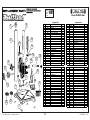
English-1097
Part # Description Qty
122035 Base 1
230171 Rubber Foot 4
305012 M6x1x12mm Bolt 1
401002 M6x1mm Nut 2
512015 #10 x 3/4" Wood Screw 4
614011 Tube 1
730173 Cord Holder 1
830176 Main Housing 1
930172 Triangular Knob 1
10 23004 Metal Tool Holder 1
11 26001 Pinion Rack 1
12 30156 Pinion Gear 1
13 10013 Spring 1
14 30158 Depth Gauge 1
15 30170 Depth Stop Collar 1
16 05010 Lock Screw M6 x 1 x 12mm 1
17 20025 Handle 1
18 30178 Handle Knob 1
19 26000 Handle Collar 1
20 34008 S-Style Knob with Brass Screw 1
21 40023 M5x0.8x12mm Brass Screw 1
22 30256 3/4"x12 Collet Nut 1
23 30257 17x1.5mm Collet Nut 1
Français-1097
N° de pièce Description Qté
122035 Base 1
230171 Pieds en caoutchouc 4
305012 Boulon M6x1x12mm 1
401002 Écrou M6x1mm 2
512015 Vis à bois n° 10 x 3/4 po 4
614011 Tube d'acier 1
730173 Passe-fil 1
830176 Boîtier principal 1
930172 Bouton triangulaire 1
10 23004 Porte-outil métallique 1
11 26001 Pignon crémaillère 1
12 30156 Pignon satellite 1
13 10013 Ressort 1
14 30158 Jauge de profondeur 1
15 30170 Collet de butée de profondeur 1
16 05010 Vis de blocage M6 x 1 x 12mm 1
17 20025 Poignée 1
18 30178 Bouton de poignée 1
19 26000 Collier de poignée 1
20 34008
Bouton en « S » avec vis en laiton
1
21 40023 Vis en laiton M5x0.8x12mm 1
22 30256 Écrous de collet 3/4 po x12 1
23 30257 Écrous de collet 17x1.5mm 1
Español-1097
Comnte # Descripción Cant
122035 Base 1
230171 Patas de goma 4
305012 Perno M6x1x12mm 1
401002 Tuerca M6x1mm 2
512015
Tornillos para madera #10 3/4 pulgada
4
614011 Tubo de acero 1
730173 Soporte del cable 1
830176 Cuerpo principal 1
930172 Perilla triangular 1
10 23004
Soporte metálico para herramienta
1
11 26001 Engranaje recto 1
12 30156 Rueda de engranaje 1
13 10013 Resorte 1
14 30158 Medidor de profundidad 1
15 30170 Tope de profundidad 1
16 05010
Tornillo de fijación M6 x 1 x 12mm
1
17 20025 Manija 1
18 30178 Perilla de la manija 1
19 26000 Cuello de la manija 1
20 34008
Perilla tipo S con tornillo de bronce
1
21 40023
Tornillo de bronce M5x0.8x12mm
1
22 30256
Tuerca de seguridad 3/4 pulgada x12
1
23 30257
Tuerca de seguridad 17x1.5mm
1
Deutsch-1097
Teile # Bezeichnung Menge
122035 Grundplatte 1
230171 Gummifuß 4
305012 Schraube, M6 x 1 x 12mm 1
401002 Mutter, M6 x 1mm 2
512015
Flachkopfschraube, # 10 x ¾ Zoll
4
614011 Rundsäule 1
730173 Kabelführung 1
830176 Gehäuse - Oberteil 1
930172 3-eckige Griffschraube 1
10 23004 Maschinenaufnahme, Metall 1
11 26001 Zahnradstange 1
12 30156 Ritzel 1
13 10013 Feder 1
14 30158 Tiefenmesser 1
15 30170 Manschette für Tiefenstopp 1
16 05010
Feststellschraube, M6 x 1 x 12mm
1
17 20025 Griffstange 1
18 30178 Griffknopf 1
19 26000 Griffaufnahme 1
20 34008 S-förmige Griffschraube 1
21 40023
Messingschraube, M5 x 0,8 x 12mm
1
22 30256 Spannzangenmutter 3/4 x 12 1
23 30257
Spannzangenmutter 17 x 1,5mm
1
1
2 1 0 1 2
2
1
0
1
2
6 5 4 3 2 1 0 1 2 3 4 5 6
2
1
0
1
2
7
3
5
8
4
6
11
10
16
917
12
18
13
19
14
20 15
21
22 23
-
 1
1
-
 2
2
-
 3
3
-
 4
4
-
 5
5
-
 6
6
-
 7
7
-
 8
8
-
 9
9
-
 10
10
-
 11
11
-
 12
12
-
 13
13


in anderen Sprachen
- English: Milescraft 1097 User manual
- français: Milescraft 1097 Manuel utilisateur
- español: Milescraft 1097 Manual de usuario
Verwandte Artikel
-
Milescraft 1097 Benutzerhandbuch
-
Milescraft DrillMate Handheld Benchtop Drill Press Bedienungsanleitung
-
-
-
Milescraft EuroHingeJig Concealed Hinge Jig Benutzerhandbuch
-
Milescraft 1341 Benutzerhandbuch
-
-
Milescraft 1340 Benutzerhandbuch
-
-
Milescraft 1225 Benutzerhandbuch