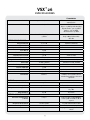
Peavey 26 Benutzerhandbuch
- Kategorie
- Audio-Equalizer
- Typ
- Benutzerhandbuch
Dieses Handbuch eignet sich auch für

www.peavey.com
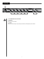
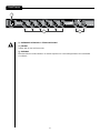
VSX
™
26
Digital Loudspeaker
Processor
Operating
Manual

2
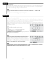
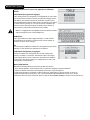
Intended to alert the user to the presence of uninsulated “dangerous voltage” within the product’s
enclosure that may be of sufficient magnitude to constitute a risk of electric shock to persons.
Intended to alert the user of the presence of important operating and maintenance (servicing)
instructions in the literature accompanying the product.
Risk of electrical shock — DO NOT OPEN!
To reduce the risk of electric shock, do not remove cover. No user serviceable parts inside.
Refer servicing to qualified service personnel.
Este símbolo tiene el propósito, de alertar al usuario de la presencia de “(voltaje) peligroso” sin
aislamiento dentro de la caja del producto y que puede tener una magnitud suficiente como para
constituir riesgo de descarga eléctrica.
Este símbolo tiene el propósito de alertar al usario de la presencia de instruccones importantes sobre la
operación y mantenimiento en la información que viene con el producto.
Riesgo de descarga eléctrica ¡NO ABRIR!
Para disminuír el riesgo de descarga eléctrica, no abra la cubierta. No hay piezas útiles
dentro. Deje todo mantenimiento en manos del personal técnico cualificado.
Ce symbole est utilisé dans ce manuel pour indiquer à l’utilisateur la présence d’une tension dangereuse
pouvant être d’amplitude suffisante pour constituer un risque de choc électrique.
Ce symbole est utilisé dans ce manuel pour indiquer à l’utilisateur qu’il ou qu’elle trouvera d’importantes
instructions concernant l’utilisation et l’entretien de l’appareil dans le paragraphe signalé.
Risques de choc électrique — NE PAS OUVRIR!
Afin de réduire le risque de choc électrique, ne pas enlever le couvercle. Il ne se trouve
à l’intérieur aucune pièce pouvant être reparée par l’utilisateur. Confiez I’entretien et la réparation de
l’appareil à un réparateur Peavey agréé.
Dieses Symbol soll den Anwender vor unisolierten gefährlichen Spannungen innerhalb des Gehäuses
warnen, die von Ausreichender Stärke sind, um einen elektrischen Schlag verursachen zu können.
Dieses Symbol soll den Benutzer auf wichtige Instruktionen in der Bedienungsanleitung aufmerksam
machen, die Handhabung und Wartung des Produkts betreffen.
Risiko — Elektrischer Schlag! Nicht öffnen!
Um das Risiko eines elektrischen Schlages zu vermeiden, nicht die Abdeckung enfernen.
Es befinden sich keine Teile darin, die vom Anwender repariert werden könnten. Reparaturen nur von
qualifiziertem Fachpersonal durchführen lassen.

3
When using electrical products, basic cautions should always be followed, including the following:
1. Read these instructions.
2. Keep these instructions.
3. Heed all warnings.
4. Follow all instructions.
5. Do not use this apparatus near water.
6. Clean only with a dry cloth.
7. Do not block any of the ventilation openings. Install in accordance with manufacturer’s instructions.
8. Do not install near any heat sources such as radiators, heat registers, stoves or other apparatus (including amplifiers)
that produce heat.
9. Do not defeat the safety purpose of the polarized or grounding-type plug. A polarized plug has two blades with one
wider than the other. A grounding type plug has two blades and a third grounding plug. The wide blade or third prong is
provided for your safety. If the provided plug does not fit into your outlet, consult an electrician for replacement of the
obsolete outlet.
10. Protect the power cord from being walked on or pinched, particularly at plugs, convenience receptacles, and the point
they exit from the apparatus.
11. Only use attachments/accessories provided by the manufacturer.
12. Use only with a cart, stand, tripod, bracket, or table specified by the manufacturer, or sold with the apparatus. When a
cart is used, use caution when moving the cart/apparatus combination to avoid injury from tip-over.
13. Unplug this apparatus during lightning storms or when unused for long periods of time.
14. Refer all servicing to qualified service personnel. Servicing is required when the apparatus has been damaged in any
way, such as power-supply cord or plug is damaged, liquid has been spilled or objects have fallen into the apparatus,
the apparatus has been exposed to rain or moisture, does not operate normally, or has been dropped.
15. Never break off the ground pin. Write for our free booklet “Shock Hazard and Grounding.” Connect only to a power
supply of the type marked on the unit adjacent to the power supply cord.
16. If this product is to be mounted in an equipment rack, rear support should be provided.
17. Note for UK only: If the colors of the wires in the mains lead of this unit do not correspond with the terminals in your
plug‚ proceed as follows:
a) The wire that is colored green and yellow must be connected to the terminal that is marked by the letter E‚ the earth
symbol‚ colored green or colored green and yellow.
b) The wire that is colored blue must be connected to the terminal that is marked with the letter N or the color black.
c) The wire that is colored brown must be connected to the terminal that is marked with the letter L or the color red.
18. This electrical apparatus should not be exposed to dripping or splashing and care should be taken not to place objects
containing liquids, such as vases, upon the apparatus.
19. Exposure to extremely high noise levels may cause a permanent hearing loss. Individuals vary considerably in suscep-
tibility to noise-induced hearing loss, but nearly everyone will lose some hearing if exposed to sufficiently intense noise
for a sufficient time. The U.S. Government’s Occupational Safety and Health Administration (OSHA) has specified the
following permissible noise level exposures:
Duration Per Day In Hours Sound Level dBA, Slow Response
8 90
6 92
4 95
3 97
2 100
1 1⁄2 102
1 105
1⁄2 110
1⁄4 or less 115
According to OSHA, any exposure in excess of the above permissible limits could result in some hearing loss. Ear plugs or protectors to
the ear canals or over the ears must be worn when operating this amplification system in order to prevent a permanent hearing loss, if
exposure is in excess of the limits as set forth above. To ensure against potentially dangerous exposure to high sound pressure levels, it is
recommended that all persons exposed to equipment capable of producing high sound pressure levels such as this amplification system be
protected by hearing protectors while this unit is in operation.

4
:
1. Lesen Sie sich diese Anweisungen durch.
2. Bewahren Sie diese Anweisungen auf.
3. Beachten Sie alle Warnungen.
4. Befolgen Sie alle Anweisungen.
5. Setzen Sie dieses Gerät nicht in der Nähe von Wasser ein.
6. Reinigen Sie es nur mit einem trockenen Tuch.
7. Blockieren Sie keine der Lüftungsöffnungen. Führen Sie die Installation gemäß den Anweisungen des Herstellers durch.
8. Installieren Sie das Gerät nicht neben Wärmequellen wie Heizungen, Heizgeräten, Öfen oder anderen Geräten (auch Verstärkern),
die Wärme erzeugen.
9. Beeinträchtigen Sie nicht die Sicherheitswirkung des gepolten Steckers bzw. des Erdungssteckers. Ein gepolter Stecker weist
zwei Stifte auf, von denen einer breiter ist als der andere. Ein Erdungsstecker weist zwei Stifte und einen dritten Erdungsstift auf.
Der breite Stift bzw. der dritte Stift dient Ihrer Sicherheit. Sollte der beiliegende Stecker nicht in Ihre Steckdose passen, wenden
Sie sich bitte an einen Elektriker, um die ungeeignete Steckdose austauschen zu lassen.
10. Schützen Sie das Netzkabel, sodass niemand darauf tritt oder es geknickt wird, insbesondere an Steckern oder Buchsen und
ihren Austrittsstellen aus dem Gerät.
11. Verwenden Sie nur die vom Hersteller erhältlichen Zubehörgeräte oder Zubehörteile.
12. Verwenden Sie nur einen Wagen, Stativ, Dreifuß, Träger oder Tisch, der den Angaben des Herstellers entspricht oder zusammen
mit dem Gerät verkauft wurde. Wird ein Wagen verwendet, bewegen Sie den Wagen mit dem darauf befindlichen Gerät besonders
vorsichtig, damit er nicht umkippt und möglicherweise jemand verletzt wird.
13. Trennen Sie das Gerät während eines Gewitters oder während längerer Zeiträume, in denen es nicht benutzt wird, von der
Stromversorgung.
14. Lassen Sie sämtliche Wartungsarbeiten von qualifizierten Kundendiensttechnikern durchführen. Eine Wartung ist erforderlich,
wenn das Gerät in irgendeiner Art beschädigt wurde, etwa wenn das Netzkabel oder der Netzstecker beschädigt wurden,
Flüssigkeit oder Gegenstände in das Gerät gelangt sind, das Gerät Regen oder Feuchtigkeit ausgesetzt wurde, nicht normal
arbeitet oder heruntergefallen ist.
15. Der Erdungsstift darf nie entfernt werden. Auf Wunsch senden wir Ihnen gerne unsere kostenlose Broschüre „Shock Hazard and
Grounding“ (Gefahr durch elektrischen Schlag und Erdung) zu. Schließen Sie nur an die Stromversorgung der Art an, die am
Gerät neben dem Netzkabel angegeben ist.
16. Wenn dieses Produkt in ein Geräte-Rack eingebaut werden soll, muss eine Versorgung über die Rückseite eingerichtet werden.
17. Hinweis – Nur für Großbritannien: Sollte die Farbe der Drähte in der Netzleitung dieses Geräts nicht mit den Klemmen in Ihrem
Stecker übereinstimmen, gehen Sie folgendermaßen vor:
a) Der grün-gelbe Draht muss an die mit E (Symbol für Erde) markierte bzw. grüne oder grün-gelbe Klemme angeschlossen
werden.
b) Der blaue Draht muss an die mit N markierte bzw. schwarze Klemme angeschlossen werden.
c) Der braune Draht muss an die mit L markierte bzw. rote Klemme angeschlossen werden.
18. Dieses Gerät darf nicht ungeschützt Wassertropfen und Wasserspritzern ausgesetzt werden und es muss darauf geachtet
werden, dass keine mit Flüssigkeiten gefüllte Gegenstände, wie z. B. Blumenvasen, auf dem Gerät abgestellt werden.
19. Belastung durch extrem hohe Lärmpegel kann zu dauerhaftem Gehörverlust führen. Die Anfälligkeit für durch Lärm bedingten
Gehörverlust ist von Mensch zu Mensch verschieden, das Gehör wird jedoch bei jedem in gewissem Maße geschädigt, der über
einen bestimmten Zeitraum ausreichend starkem Lärm ausgesetzt ist. Die US-Arbeitsschutzbehörde (Occupational and Health
Administration, OSHA) hat die folgenden zulässigen Pegel für Lärmbelastung festgelegt:
Dauer pro Tag in Stunden Geräuschpegel dBA, langsame Reaktion
8 90
6 92
4 95
3 97
2 100
1
1
⁄
2
102
1 105
1
⁄
2
110
1
⁄
4
oder weniger 115
Laut OSHA kann jede Belastung über den obenstehenden zulässigen Grenzwerten zu einem gewissen Gehörverlust führen. Sollte
die Belastung die obenstehenden Grenzwerte übersteigen, müssen beim Betrieb dieses Verstärkungssystems Ohrenstopfen oder
Schutzvorrichtungen im Gehörgang oder über den Ohren getragen werden, um einen dauerhaften Gehörverlust zu verhindern. Um sich vor
einer möglicherweise gefährlichen Belastung durch hohe Schalldruckpegel zu schützen, wird allen Personen empfohlen, die mit Geräten
arbeiten, die wie dieses Verstärkungssystem hohe Schalldruckpegel erzeugen können, beim Betrieb dieses Geräts einen Gehörschutz zu tra-
gen.

5
1. Lire ces instructions.
2. Gardez ce manuel pour de futures références.
3. Prétez attention aux messages de précautions de ce manuel.
4. Suivez ces instructions.
5. N’utilisez pas cette unité proche de plans d’eau.
6. N’utilisez qu’un tissu sec pour le nettoyage de votre unité.
7. N’obstruez pas les systèmes de refroidissement de votre unité et installez votre unité en fonction des instructions
de ce manuel.
8. Ne positionnez pas votre unité à proximité de toute source de chaleur.
9. Connectez toujours votre unité sur une alimentation munie de prise de terre utilisant le cordon d’alimentation
fourni.
10. Protégez les connecteurs de votre unité et positionnez les cablages pour éviter toutes déconnexions accidentelles.
11. N’utilisez que des fixations approuvées par le fabriquant.
12. Lors de l’utilsation sur pied ou pole de support, assurez dans le cas de déplacement de l’ensemble enceinte/
support de prévenir tout basculement intempestif de celui-ci.
13. Il est conseillé de déconnecter du secteur votre unité en cas d’orage ou de durée prolongée sans utilisation.
14. Seul un technicien agréé par le fabriquant est à même de réparer/contrôler votre unité. Celle-ci doit être contrôlée si
elle a subit des dommages de manipulation, d’utilisation ou de stockage (humidité,…).
15. Ne déconnectez jamais la prise de terre de votre unité.
16. Si votre unité est destinée a etre montée en rack, des supports arriere doivent etre utilises.
17. Note pour les Royaumes-Unis: Si les couleurs de connecteurs du cable d’alimentation ne correspond pas au guide
de la prise secteur, procédez comme suit:
a) Le connecteur vert et jaune doit être connectrer au terminal noté E, indiquant la prise de terre ou correspondant
aux couleurs verte ou verte et jaune du guide.
b) Le connecteur Bleu doit être connectrer au terminal noté N, correspondnat à la couleur noire du guide.
c) Le connecteur marron doit être connectrer au terminal noté L, correspondant à la couleur rouge du guide.
18. Cet équipement électrique ne doit en aucun cas être en contact avec un quelconque liquide et aucun objet
contenant un liquide, vase ou autre ne devrait être posé sur celui-ci.
19. Une exposition à de hauts niveaux sonores peut conduire à des dommages de l’écoute irréversibles. La suscep
-
tibilité au bruit varie considérablement d’un individu à l’autre, mais une large majorité de la population expériencera
une perte de l’écoute après une exposition à une forte puissance sonore pour une durée prolongée. L’organisme de
la santé américaine (OSHA) a produit le guide ci-dessous en rapport à la perte occasionnée:
Durée par Jour (heures) Niveau sonore moyen (dBA)
8 90
6 92
4 95
3 97
2 100
1
1
⁄
2
102
1 105
1
⁄
2
110
1
⁄
4
ou inférieur 115
D’après les études menées par le OSHA, toute exposition au delà des limites décrites ce-dessus entrainera des pertes de l’écoute chez la
plupart des sujets. Le port de système de protection (casque, oreilette de filtrage,…) doit être observé lors de l’opération cette unité ou des
dommages irréversibles peuvent être occasionnés. Le port de ces systèmes doit être observé par toutes personnes susceptibles d’être expo-
sées à des conditions au delà des limites décrites ci-dessus.

6
1. Lea estas instrucciones.
2. Guarde estas instrucciones.
3. Haga caso de todos los consejos.
4. Siga todas las instrucciones.
5. No usar este aparato cerca del agua.
6. Limpiar solamente con una tela seca.
7. No bloquear ninguna de las salidas de ventilación. Instalar de acuerdo a las instrucciones del fabricante.
8. No instalar cerca de ninguna fuente de calor como radiadores, estufas, hornos u otros aparatos (incluyendo amplificadores)
que produzcan calor.
9. No retire la patilla protectora del enchufe polarizado o de tipo “a Tierra”. Un enchufe polarizado tiene dos puntas, una de
ellas más ancha que la otra. Un enchufe de tipo “a Tierra” tiene dos puntas y una tercera “a Tierra”. La punta ancha (la
tercera ) se proporciona para su seguridad. Si el enchufe proporcionado no encaja en su enchufe de red, consulte a un
electricista para que reemplaze su enchufe obsoleto.
10. Proteja el cable de alimentación para que no sea pisado o pinchado, particularmente en los enchufes, huecos, y los puntos
que salen del aparato.
11. Usar solamente añadidos/accesorios proporcionados por el fabricante.
12. Usar solamente un carro, pie, trípode, o soporte especificado por el fabricante, o vendido junto al aparato. Cuando se use
un carro, tenga cuidado al mover el conjunto carro/aparato para evitar que se dañe en un vuelco. No suspenda esta caja de
ninguna manera.
13. Desenchufe este aparato durante tormentas o cuando no sea usado durante largos periodos de tiempo.
14. Para cualquier reparación, acuda a personal de servicio cualificado. Se requieren reparaciones cuando el aparato ha sido
dañado de alguna manera, como cuando el cable de alimentación o el enchufe se han dañado, algún líquido ha sido
derramado o algún objeto ha caído dentro del aparato, el aparato ha sido expuesto a la lluvia o la humedad, no funciona de
manera normal, o ha sufrido una caída.
15. Nunca retire la patilla de Tierra.Escríbanos para obtener nuestro folleto gratuito “Shock Hazard and Grounding” (“Peligro
de Electrocución y Toma a Tierra”). Conecte el aparato sólo a una fuente de alimentación del tipo marcado al lado del cable
de alimentación.
16. Si este producto va a ser enracado con más equipo, use algún tipo de apoyo trasero.
17. Nota para el Reino Unido solamente: Si los colores de los cables en el enchufe principal de esta unidad no corresponden
con los terminales en su enchufe‚ proceda de la siguiente manera:
a) El cable de color verde y azul debe ser conectado al terminal que está marcado con la letra E‚ el símbolo de Tierra
(earth)‚ coloreado en verde o en verde y amarillo.
b) El cable coloreado en azul debe ser conectado al terminal que está marcado con la letra N o el color negro.
c) El cable coloreado en marrón debe ser conectado al terminal que está marcado con la letra L o el color rojo.
18. Este aparato eléctrico no debe ser sometido a ningún tipo de goteo o salpicadura y se debe tener cuidado para no poner
objetos que contengan líquidos, como vasos, sobre el aparato.
19. La exposición a altos niveles de ruido puede causar una pérdida permanente en la audición. La susceptibilidad a la pérdida
de audición provocada por el ruido varía según la persona, pero casi todo el mundo perderá algo de audición si se expone
a un nivel de ruido suficientemante intenso durante un tiempo determinado. El Departamento para la Salud y para la
Seguridad del Gobierno de los Estados Unidos (OSHA) ha especificado las siguientes exposiciones al ruido permisibles:
Duración por Día en Horas Nivel de Sonido dBA, Respuesta Lenta
8 90
6 92
4 95
3 97
2 100
1
1
⁄
2
102
1 105
1
⁄
2
110
1
⁄
4
o menos 115
De acuerdo al OSHA, cualquier exposición que exceda los límites arriba indicados puede producir algún tipo de pérdida en la audición.
Protectores para los canales auditivos o tapones para los oídos deben ser usados cuando se opere con este sistema de sonido para preve-
nir una pérdida permanente en la audición, si la exposición excede los límites indicados más arriba. Para protegerse de una exposición a
altos niveles de sonido potencialmente peligrosa, se recomienda que todas las personas expuestas a equipamiento capaz de producir altos
niveles de presión sonora, tales como este sistema de amplificación, se encuentren protegidas por protectores auditivos mientras esta uni-
dad esté operando.

7
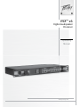
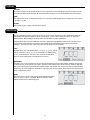
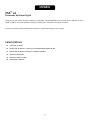
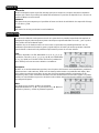
The VSX 26 is a fully progammable 32-bit audio processing and louspeaker management control system. Considerably more
powerful than similarly priced units, the VSX 26 provides a versatile and economical alternative for system designers.
Please read this guide carefully to ensure your personal safety as well as the safety of your equipment.
◆
◆
◆
◆
◆
◆

8
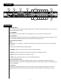
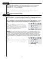
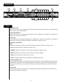
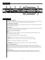
Mic level input for measuring mic. Phantom power may be selected in software. May be used as a extra input
and routed through the system.
Rotate clockwise or counter clockwise to scroll through screens. Push to enter or confirm selection.
This screen gives a graphical representation of unit configuration and parameter settings. The layout of the screen
and the information displayed will depend on the function being monitored or set.
Configurations are selected here. Parameter selection for inputs, signal generator, stereo/mono, routing matrix,
and outputs.
parameter selection of input or output equalizers
parameter selection of input or output compressor/limiters
parameters of the bandpass modules for each output or configured crossover
delay time and polarity for each input or output
saving and loading of presets as well as default configuration
LEDs indicate active or muted channel conditions. Mute switches are provided to manually mute inputs or
outputs. Signal LEDs are Green for normal signal level, Yellow at +18 dBu output and Red at +20 dBu, just before
the onset of clipping.
Connection of memory stick/jump drive for preset storage and system update and computer connection for
controlling the unit from the GUI. The slot supports USB 2.0 memory sticks whose current draw is 150 ma or
less.
1 2 3
4
5
5
6
6

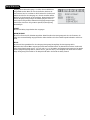
9
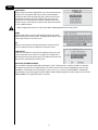
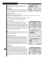
XLR male line level outputs
XLR female line level inputs. Input A may be switched to AES digital input via software.
1
2 3

10
switchs between –10 dBV or +4 dBV inputs. The +4
dB position should be considered the “normal” position and should
be used with professional systems. The -10 dB position allows the
unit to be driven with “hi-fi” level equipment or directly from a CD
player.
toggle on/off.
operation is selectable on input A.
controls digital processing headroom and is adjustable from 0 dB through –100 dB. This adjustment is best left
as high as possible but may be adjusted as necessary.
is variable from –6 dB to +6 dB and is used to match analog input sensitivity as necessary.
Exit this screen by selecting “” and pressing the data wheel or pressing the “setup” button.
Toggles between Stereo and Mono. Selecting Stereo associates the
A/B channel inputs. It does not affect the output channels. When
engaged in “stereo” adjusting a parameter on channel A will make
a corresponding adjustment on Ch B. This may be most useful when
adjusting GEQs, Delay or Dynamic settings. Preliminary adjustments
can be made to both channels in this manner and then the switch
can be toggled to mono allowing further independent adjustment of
single inputs. The switch may be toggled again to link up the dynamic
sections for stereo tracking of the comp/limiters.
Allows engaging the +48 V phantom power as well as adjusting the
Mic gain range from 23 dB to 67 dB of gain. Select “done” or press
“setup” to escape to the main screen.
This screen selects the parameters for the signal generator. Pink,
White or Sine may be selected. When Sine is selected the frequency
of the sine wave may be adjusted for 20 Hz to 20 kHz. The output
level may be adjusted by highlighting the fader graphic and adjusting
the Level control. An In/Out button is provided to turn on and off the
generator. The screen may be exited by selecting “done” or pressing
the “setup button. The Generator must be assigned to an output of
your choice with the Matrix. A single B and pass filter can also be
assigned to that output and the skirts may be adjusted to provide
limited bandwidth noise for testing purposes.
The matrix provides the method to assign inputs to outputs. In the
default configuration NO SIGNAL IS PASSED through the unit until
some selection in the matrix is made. This prevents potentially
destructive signals from reaching the wrong outputs. The inputs
are represented by the rows and the outputs by the columns. Most
users will commonly assign crossovers in the setup screen so that
only a single input assignment will be necessary. In addition to the
line inputs the RTA and GEN inputs are assigned in this screen. To
continue from the matrix you must exit from the upper left or the
lower right squares.

11
Selecting this button takes you to the preset configuration page.
The VSX™ is pre-programmed with eight configuration templates
representing the most frequently used crossover possibilities. As you
scroll through the configuration presets you will see and can adjust
the basic filter types (only symmetrical choices may be made here).
Center frequencies of those filters and a graphic representation
of the filters will be displayed. You must enter “OK” to accept the
selection. Selecting and pressing Exit or pressing the Setup button
will return you to the main screen. Upon returning to the main screen
you will see the graphic representation of your selection.
Output levels may be adjusted on this page. Press “done” or push
the setup button to return to the main screen.
Inputs A & B or outputs 1-6 should be selected on the top of the
screen. While on the top of the screen push the data wheel and an
arrow appears. Rotate the wheel to select which input or output you
wish to adjust.
on inputs
This switch gives a paragraphic action to the 27 band equalizer. It toggles between 1/6, 1/3, 1/2 and 1
octave bandwidth for the width of the individual filters. Bandwidth is defined 3 dB from the peak or minimum
amplitude and greatly affects the way the adjacent filters combine or stay independent. Wider bandwidth is
most useful when adjusting the overall curve of the speaker to the room or tone control as ripple is minimized.
The 1/6
th
bandwidth has the least filter skirt combining and should be used for feedback control only.
As you scroll through the 27 positions the knob graphic becomes filled and the corresponding frequency is
listed on the bottom left. Press the data wheel to select a frequency to adjust.
After selecting a frequency, rotating the data wheel allows boosting or cutting the amplitude of the selected
frequency +/- 15 dB in .5 dB increments.
Pressing the EQ button is a short cut to return to the top of the screen.

12
Select 1-6 on the top of the EQ screen.
Select any of the five independent filters to use.
Choices are: Parametric, Notch, Allpass1, Allpass2, Horn EQ, LPF-6, LPF-12, HPF-6, HPF-12, Low Shelf, High Shelf
and Bandpass. Depending on the filter selected various options for adjustment are presented in the window.
Frequency, BW (in oct), Level
Frequency, BW (in oct). Notch has a fixed attenuation on minus
infinity and the BW is defined 3 dB from unity.
Frequency
Frequency and Bandwidth
Turnover Frequency and Level
Frequency
Frequency and Q
Frequency and Level
Center Frequency and Bandwidth
Inputs A and B or outputs 1-6 should be selected on the top of the screen. While on the top of the screen push
the data wheel and an arrow appears. Rotate the wheel to select which input or output you wish to adjust and
press the data wheel. Dynamics in the input channels may be linked in pairs for stereo tracking on the Input
pages on the Setup/Configuration screen. Most users should use the dynamics on the outputs as Limiters to
protect speakers and amplifiers and as compressors on the inputs should this type of tonal modification be
necessary.
The threshold is adjustable in .5 dB steps from –76 dBu to +24 dBu.
This control determines the minimum level when the compressor
begins to limit the dynamic range. The compressor has no affect on
the signal as long as the signal strength is below the threshold point.
Once it passes the threshold point, the compressor begins to limit
the dynamic range of the output according to the value set by the
Ratio control.
The ratio determines how strong the limiting becomes once the threshold is crossed. Values of 1:1 (no
compression) to 20:1 are possible. Ratios of 10:1 and above should be selected for speaker protection.
The attack function sets the amount of time for the compressor to respond once the threshold has been crossed.
Specifying this value allows the user to determine whether the compressor responds as a peak or RMS unit as
very short attack times consider only peaks while times above 50 ms average these peaks and result in RMS
response. We recommend attack times of between 50 ms - 100 ms be used when setting the limiters to protect
the speakers from being overdriven by the power amps. It is the average power long term that causes speaker
burn out. The transient peaks usually cause little damage if kept inside the speaker’s band limits.

13
The Release value sets the amount of time for the compressor to recover from the compressed state once the
level falls below the threshold level. We recommend release times of 5x to 10x the Attack time in normal use.
This adjustment serves to compensate for the loss in average signal strength due to compression. The range is
–100 dB to + 30 dB.
This button toggles to bypass the dynamics section.
The output channel numbers appear across the top of the screen. Depending on the configuration template
chosen they may appear together as blocks representing 2-way, 3-way or 4-way crossovers or singly as a
Bandpass filter. After making a selection rotate the data wheel to adjust parameters.
Each bandpass filter associated with the crossover is represented graphically on the screen. The two slopes
represent the lower and upper frequencies of the bandpass and the plateau represents the level of the
bandpass. The intersection of slopes represents the electrical crossover point(s).
Available filters are: Flat, Butterworth 6, 12, 18, 24, 30, 36, 42, and 48
dB/oct.; Bessell 12, 18, 24, 30, 36, 42 and 48 dB/oct; Linkwitz-Riley
12, 24, 36 and 48 dB/oct. The user is free to mix and match filter
types to create symmetrical or asymmetrical crossovers.
The VSX™ 26 is a very powerful tool and as such the frequency points are independent, allowing over-lapping
or under-lapping as the system may require. The lowest and highest slopes in the chain are useful as high and
low system cutoff filters to prevent low frequency rumble and speaker over excursion as well as high frequency
interference. The filter points are selectable in 1 Hz steps from 20 Hz to 20kHz. They may also be selected in the
setup/configuration screen.
The levels of the crossover sections are independently adjustable
from –15 dB to +15 db in .5 dB steps. Move the indicator to the
plateau and the level parameter appears.

14
Inputs A and B or outputs 1-6 should be selected on the top of the
screen. While on the top of the screen push the data wheel and an
arrow appears. Rotate the wheel to select which input or output
you wish to adjust. Push the data wheel to accept. Normally the
output delays are used to align the phase response of the drivers in
a system while the input delays are useful for adding delay to the
entire system(s).
Toggles to engage or bypass the delay
Toggles to invert the polarity from the present state. It may become necessary to flip the polarity many times
while adjusting the delay time or adjusting the cut-off rate of the filters. It is conveniently located on this page
for that purpose.
Adds delay to the selected input or output. The delay is displayed in milliseconds, feet and meters and
automatically calculates each as the data wheel is rotated. The range of each delay is 340 ms, 379.09 feet and
115.59 meters. The input delay amount will be added to the output delay amount for a possible 680 ms, 758.18
feet and 231.18 meters should a very long delay be necessary. One example would be for use with delay towers.

15
Allows saving the current configuration to one of 8 internal memory
positions or to an external USB memory stick. If external USB is
selected the VSX™ will automatically write a folder and file to the
stick without disturbing other files/folders that may be present
on the stick. It is not necessary to dedicate a memory stick to the
exclusive service of the VSX. Files from the stick may be transferred
to a PC or MAC computer.
Configuration presets are stored in the folder: on the memory stick.
Selecting this function opens a alpha numeric keyboard. The VSX
allows 8 characters to name the file. The {Right Arrow} button on the
bottom right returns to the Save screen.
Must be selected and the data wheel pushed to actually save the
preset. You will be asked to confirm this on the next screen.
Rotate the data wheel to select from the eight internal presets and
from an external memory stick, if it is plugged in. Press OK and it
will load the preset to the current preset. A confirmation screen will
appear before overwriting the current preset.
Press and hold in the data wheel while powering up. Insert a memory stick or connect via USB to a computer.
The VSX will search for files and will display a list. Select the desired version by highlighting it and press the
Data Wheel. A confirmation screen will appear. Cursor over to “yes” and press the Data Wheel. The VSX will
automatically perform the upgrade from here. When downloading the upgrade from the web place it in a folder:
. The upgrade file will be a .bin file.

16
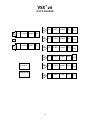
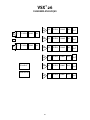
A
B
27 GEQ
27 GEQ
COMP
COMP
DLY
DLY
5 PEQ COMP
DLY
5 PEQ
5 PEQ
COMP
COMP
DLY
DLY
5 PEQ
5 PEQ
COMP
COMP
DLY
DLY
5 PEQ COMP DLY
BP
BP
BP
BP
BP
BP
FB
FB
RTA INPUT
GENERAT OR
ST /M
M IX
M IX
M IX
M IX
M IX
M IX
OUT
OUT
OUT
OUT
OUT
OUT

17
3 inputs/6 outputs RTA Mic input can be summed with
Line inputs.
2 inputs/6 outputs LED STATUS:
Red = -0.5 dBFS and higher (Clip)
Red & Green = -4 to -0.5 dBFS
Green = -4 to -40 dBFS
Off = below -40 dBFS
Front panel switch and LED for each input and
output
LED STATUS:
Red = Muted
Off = On
-6 to +6 dB Software controlled
+24 dBu or -10 dBV Software selectable
4.4 k ohms Electronically balanced
24 dB
55 dB
-90 dB 20 Hz to 20 kHz
110 dB A-weighted 150 ohm input termination
+20 to +60 dB Approximately 1/2 dB steps
+2 dBu (.98Vrms) Gain = 60 dB, 22K BW
2.2 k ohm Electronically balanced
55 dB
-128 dB A-weighted 150 ohm input termination
+48 volts Software controlled
On XLR 1 Software selectable between left
channel analog line input
+24 dBu Balanced
150 ohms Electronically balanced
600 ohms Maximum output @ 600 ohms =
22.5 dBu
105 dB A-weighted
0.007 % 20 Hz to 20 kHz, 22 kHz BW filter,
+4 dBu signal with 20 dB headroom
20 Hz to 20 kHz ± 0.5 dBr referenced at 1 kHz
105 dB A-weighted, 150 ohm input
termination
< 1 mS Propagation delay from input to
output

18
48 kHz QUANTIZATION 24-bit 256 x-over-
sampled Delta-Sigma AD, DA
~100 32-bit MIP Uses Analog Devices BLACKFIN
processors, 40-bit accumulators
500 MHZ
2.0 PC, Memory Stick, PDA Connection
19" (48.26 cm) W
12.25" (31.12 cm) D
3.5" (8.89 cm) H
without connectors
11.6 lbs. (5.26 kg)
100 ~ 240 VAC 47 ~ 63 Hz Universal Power Supply
14 watts @120 V 163 mA
47 Btu (11.8 kcal) @ 120 V
UL, CUL, CE, FCC part 15, Class B Pending
Unless otherwise noted:
1. All specications are typical for any channel(s).
2. All measurements are made in the digital domain.
3. All specications are for an AC line input of 120 volts RMS.
4. All input measurements are made using a 40 ohm balanced source impedance at +24 dBu full scale.
5. All measurements are made with gain/attenuation set for unity.

19
Der VSX 26 ist ein voll programmierbares 32-Bit-Audioprozessor- und Lautsprecher-Managementsystem. Der VSX 26 eine
vielseitige Lösung für Systemplaner dar.
Lesen Sie sich diese Anleitung bitte sorgfältig durch, damit sowohl Ihre Sicherheit als auch die Ihrer Ausrüstung gewährleistet
ist.
◆
◆
◆
◆
◆
◆

20
Mic-Pegeleingang für Messmikro. Über die Software kann die Phantomspeisung aktiviert werden. Kann als
zusätzlicher Eingang verwendet und durch das System geroutet werden.
Durch Drehen des Datenrads im Uhrzeigersinn bzw. umgekehrten Uhrzeigersinn kann durch die Bildschirme
gescrollt werden. Drücken Sie das Rad, um eine Auswahl einzugeben oder zu bestätigen.
Auf diesem Bildschirm werden Gerätekonfiguration und Parametereinstellungen grafisch dargestellt. Aufbau des
Bildschirms und angezeigte Informationen hängen von der überwachten bzw. eingestellten Funktion ab.
Hier werden die Konfigurationen ausgewählt. Es können Parameter für Eingänge, Signalgenerator, Stereo/Mono,
Routing-Matrix und Ausgänge gewählt werden.
Parameterauswahl für Eingangs- oder Ausgangs-Equalizer.
Parameterauswahl für Eingangs- oder Ausgangskompressor/-limiter.
Parameter der Bandpassmodule für jeden Ausgang oder jede konfigurierte Frequenzweiche.
Verzögerungszeit und Polarität für jeden Ein- bzw. Ausgang.
Speichern und Aufrufen von Presets sowie Standardkonfiguration.
LEDs zeigen an, ob ein Kanal aktiv oder stummgeschaltet ist. Über Stummschalter können Ein- bzw.
Ausgänge manuell stummgeschaltet werden. Grüne Signal-LEDs zeigen normalen Signalpegel an, gelbe einen
Signalausgang ab +18 dBu und rote ab +20 dBu (knapp unter Clipping-Schwelle).
Für den Anschluss von Memory Sticks, Jump Drives usw. zum Speichern von Presets und für System-Updates
sowie zum Anschließen an den Computer, um das Gerät über die grafische Benutzerschnittstelle steuern zu
können. Der Anschluss ist für USB 2.0 Memory Sticks mit einem Strombedarf von höchstens 150 mA ausgelegt.
1 2 3
4
5
5
6
6
Seite wird geladen ...
Seite wird geladen ...
Seite wird geladen ...
Seite wird geladen ...
Seite wird geladen ...
Seite wird geladen ...
Seite wird geladen ...
Seite wird geladen ...
Seite wird geladen ...
Seite wird geladen ...
Seite wird geladen ...
Seite wird geladen ...
Seite wird geladen ...
Seite wird geladen ...
Seite wird geladen ...
Seite wird geladen ...
Seite wird geladen ...
Seite wird geladen ...
Seite wird geladen ...
Seite wird geladen ...
Seite wird geladen ...
Seite wird geladen ...
Seite wird geladen ...
Seite wird geladen ...
Seite wird geladen ...
Seite wird geladen ...
Seite wird geladen ...
Seite wird geladen ...
Seite wird geladen ...
Seite wird geladen ...
Seite wird geladen ...
Seite wird geladen ...
Seite wird geladen ...
Seite wird geladen ...
Seite wird geladen ...
Seite wird geladen ...
-
 1
1
-
 2
2
-
 3
3
-
 4
4
-
 5
5
-
 6
6
-
 7
7
-
 8
8
-
 9
9
-
 10
10
-
 11
11
-
 12
12
-
 13
13
-
 14
14
-
 15
15
-
 16
16
-
 17
17
-
 18
18
-
 19
19
-
 20
20
-
 21
21
-
 22
22
-
 23
23
-
 24
24
-
 25
25
-
 26
26
-
 27
27
-
 28
28
-
 29
29
-
 30
30
-
 31
31
-
 32
32
-
 33
33
-
 34
34
-
 35
35
-
 36
36
-
 37
37
-
 38
38
-
 39
39
-
 40
40
-
 41
41
-
 42
42
-
 43
43
-
 44
44
-
 45
45
-
 46
46
-
 47
47
-
 48
48
-
 49
49
-
 50
50
-
 51
51
-
 52
52
-
 53
53
-
 54
54
-
 55
55
-
 56
56


Peavey 26 Benutzerhandbuch
- Kategorie
- Audio-Equalizer
- Typ
- Benutzerhandbuch
- Dieses Handbuch eignet sich auch für
in anderen Sprachen
- English: Peavey 26 User manual
- français: Peavey 26 Manuel utilisateur
- español: Peavey 26 Manual de usuario
Verwandte Artikel
-
Peavey IPR 3000 Benutzerhandbuch
-
-
-
-
Peavey PV 10 Benutzerhandbuch
-
Peavey Digitool MX32a Digital Audio Processing Unit Bedienungsanleitung
-
-
-
-
